
M
Matthew ButlerAug 1, 2025
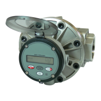
What to do if Flomec OM025 meter readings are low?
- TTyler HarrisAug 2, 2025
If your Flomec Measuring Instruments meter readings are low, it could be due to several factors. Damaged or worn rotors can cause this issue; inspect, repair, clean, or replace the rotors. Similarly, a damaged or worn measuring chamber can be responsible; inspect the measuring chamber for damage and repair it, and check the concentricity of rotor shafts within the chamber. Output signal interference is another potential cause, which can be resolved by grounding the shield of the signal cable, re-routing the cable away from high electrical energy sources, and checking all electrical terminations and wires for continuity.