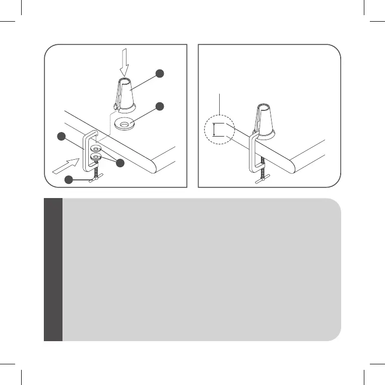
Fig.5 Fig.6
15 mm MIN
65 mm MAX
<IT>
<GB>
<DE>
<FR>
<ES>
<PT>
Fig.5/6MORSETTO- Posizionare le guarnizioni (G e H) rispettivamente sotto il supporto (F) e sul morsetto (E).
Inserire il morsetto (E) nel supporto (F) e serrarlo mediante la vite (I).
Fig.5/6CLAMP- Position the gaskets (G and H) under the support (F) and on the clamp (E), respectively. Insert
the clamp E) in the support (F) and tighten the screw (I).
Abb.5/6 KLEMME- Die Dichtungen (G und H) jeweils unter der Halterung (F) und der Klemme (E) anordnen.
Klemme (E) in die Halterung (F) einsetzen und mit Schraube (I) festziehen.
Fig.5/6ETAU- Positionner les garnitures (G et H) respectivement sous le support (F) et sur l’étau (E). Introduire
l’étau (E) dans le support (F) et le serrer au moyen de la vis (I).
Imag.5/6BORNE- Colocar las juntas (G e H) respectivamente debajo del soporte (F) y en el borne (E). Introducir
el borne (E) en el soporte (F) y apretarlo con el tornillo (I).
Fig.5/6BORNE- Colocar as guarniçoes (G e H) respectivamente em baixo do suporte (F) e no borne (E). Inserir o
borne (E) no suporte (F) e fechar com os parafusos (I).
F
G
E
H
I