Regeneration Cycle program Setting Procedure
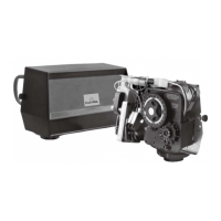
MODEL 3200 & 3210 TIMER SERIES
How To Set The Regeneration Cycle Pro-
gram:
How To Change The Length Of Rapid Rinse:
How To Change The Length Of Brine TankRefill
Time:
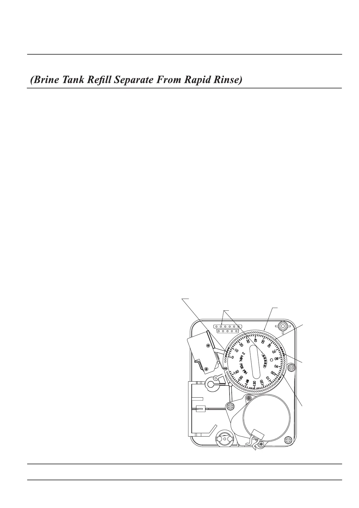
3200 & 3210 Series Timers (Figure to Right)
Timer Setting Procedure for 3200 and 3210
Timer How To Change The Length Of The
Backwash Time:
How To Change The Length Of Brine And
Rinse Time:
The regeneration cycle program on your water conditioner
has been factory preset, however, portions of the cycle or
program may be lengthened or shortened in time to suit
local conditions.
The second group of pins on the program wheel deter-
mines the Iength of time that your water conditioner will
rapid rinse. (2 min. per pin.)
To change the Iength of rapid rinse time, add or remove
pins at the higher numbered end of this section as
The second group of holes in the program wheel determines the
length of time that your water conditioner will refill the brine tank.
(2 min. per hole.)
To change the Iength of refill time, move the two pins at the end
of the second group of holes as required.
The regeneration cycle is complete when the outer microswitch
is tripped by the two pin set at end of the brine tank refill
section. The program wheel, however, will continue to rotate
until the inner micro-switch drops into the notch on the program-
wheel.
required. The number of pins times two equals the rapid rinse
time in minutes.
To expose cycle program wheel, first pull cable out of
meter dome of 3210 timers, grasp timer in upper Ieft-hand
corner and pull, releasing snap retainer and swinging
timer to the right.
To change the regeneration cycle program, the program
wheel must be removed. Grasp program wheel and
squeeze protruding Iugs toward center, Iift program wheel
off timer. (Switch arms may require movement to facilitate
removal.)
Return timer to closed position engaging snap retainer in
back plate. Make certain all electrical wires Iocate above
snap retainerpost. Reconnect meter cable.
The programwheel as shown in the drawing is in the
service position. As you Iook at the numbered side of the
program wheel, the group of pins starting at zero deter-
mines the Iength of time your unit will backwash.
FOR EXAMPLE: If there are six pins in this section, the
time of backwash will be 12 min. (2 min. per pin). To
change the Iength of backwash time, add or remove pins
as required. The number of pins times two equals the
backwash time in minutes.
The group of holes between the Iast pin in the backwash
section and the second group of pins determines the
Iength of time that your unit will brine and rinse (2 min. per
hole. )
To change the Iength of brine and rinse time,move the
rapid rinse group of pins to give more or fewer holes in
the brine and rinse section. Number of holes times two
equals brine and rinse time in minutes.
3,16725$*(
5$3,'
5,16(
6(7,21
0,1
3(53,1
%$&.:$6+6(&7,21
0,13(53,1
%5,1(5,16(
0,13(5+2/(
%5,1(
7$1.
352*5$0:+((/)25
5(*(1(5$7,21&<&/(
Page 12
 Loading...