EasyManua.ls Logo

Flow HIVE 2 - User Manual

Flow HIVE 2
13 pages
Print Icon
To Next Page IconTo Next Page
Loading...
FLOW
®
HIVE 2
ASSEMBLY GUIDE
If we look
after the bees they will look
after us, and the honey really
is an amazing bonus.
AUSTRALIAN
MADE
FLOW HIVE 2: CEDAR 6 & 7 FRAME, PAULOWNIA 6 FRAME, ARAUCARIA 6 & 7 FRAME
FLOW HIVE 2 BROOD BOX
Question and Answer IconNeed help?

Do you have a question about the Flow HIVE 2 and is the answer not in the manual?

Summary

Identifying Flow Super and Brood Box Parts

Components of a Flow Hive 2

Tools for Assembly

Roof Assembly - Cedar & Paulownia 6 Frame

Roof Assembly - Araucaria 6 Frame

Roof Assembly - Araucaria 7 Frame

Roof Assembly - Cedar 7 Frame

Flow Super Assembly

Brood Box Assembly

Brood Frame Assembly

Base Assembly

Harvesting Shelf Assembly

Leg Kit Assembly (Optional Extra)

Flow Hive 2 Configurations

Starting Your Colony Configuration

Initial setup of brood box, inner cover, and roof before adding Flow Super.

Established Colony Configuration

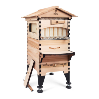
Adding Flow Super with frames once colony is strong and established.

Timber Finishes

How to Use Your Base Tray

How to Use Your Spirit Levels

Harvesting Checklist

Overview

The Flow Hive 2 is a beehive designed for easy honey harvesting. It is available in various configurations, including Cedar 6 & 7 frame, Paulownia 6 frame, and Araucaria 6 & 7 frame models, as well as a Flow Hive 2 Brood Box. The assembly process typically takes a couple of hours, and users are advised to spread out components to ensure smooth assembly. Pictorial guides are provided for identifying parts for each major component.

Key Components and Their Functions:

  • Roof: Protects the hive from the elements. Available in Cedar, Paulownia, and Araucaria wood types. The roof assembly involves screwing rails and gables together, affixing shingle panels, and securing the ridge cap. Brass wing screws are included to secure the roof in high wind areas.
  • Inner Cover: Sits beneath the roof, providing an internal ceiling for the hive. It includes a plug that can be used to control bee access to the roof during colony establishment.
  • Flow Super: This is the upper box where the Flow Frames (not included in the manual's parts list but mentioned as where they sit) are housed for honey collection. It features side observation windows with covers for monitoring the frames, a Flow Key access cover, and a latch. The Flow Super panels can be distinguished from Brood Box panels by the presence of a window cutout, stepped box joint, and metal bracing strip notch. Assembly involves attaching acrylic frame spacers, dry fitting panels, securing with screws, affixing a metal bracing strip, attaching observation windows and covers, and installing a rear window latch.
  • Queen Excluder: A grid placed between the Flow Super and the Brood Box to prevent the queen bee from entering the Flow Super and laying eggs in the honey frames.
  • Brood Box: The lower box where the queen lays eggs and the colony raises its young. It comes with brood frames (not included in the manual's parts list but mentioned as being housed within). Brood box end panels can be identified by an extra set of pilot holes on the finger joints compared to Flow Super front panels. Assembly involves dry fitting side and end panels and securing them with screws.
  • Brood Frames: These frames are assembled by laying out pieces, applying wood glue to the u-shape slots on the end panels, fitting top and bottom bars, checking for squareness, and nailing all pieces together. Comb guides are glued in only when using natural foundation.
  • Base: The foundation of the hive, which includes side panels (one with a spirit level), a front panel, a rear support beam, a rear vented cover (with spirit level), a rear panel, metal rails, a metal screen, a tray, and a landing board. It also includes footblocks for optional use if a leg kit is not installed. Assembly involves dry fitting panels, securing with screws, attaching the rear support beam and landing board, affixing metal rails, sliding in the acrylic tray, and installing the rear vented cover and metal screen.
  • Harvesting Shelf Brackets (optional): These brackets attach to the Flow Super rear window cover to create a shelf for honey jars during harvesting.
  • Leg Kit (optional): Provides a raised stand for the hive, allowing for optimal harvesting slope. It includes timber leg brackets, timber leg covers, and adjustable foot brackets.

Important Technical Specifications & Usage Features:

  • Optimal Harvesting Slope: The Flow Hive 2 is designed to be set up with a 3° slope towards the honey outlets for optimal harvesting. Inbuilt spirit levels on the base's side and rear panels indicate when this slope is achieved. This can be set using either the supplied footblocks or the optional leg kit.
  • Honey Jar Capacity: Each Flow Frame can hold up to 2.3L / 3.2kg (2.4qt) of honey.
  • Timber Finishes:
    • Araucaria & Paulownia: Recommended to paint the outside of the hive with a paint primer followed by a good quality exterior grade paint for weather protection and increased life.
    • Western Red Cedar: To preserve the natural timber finish, a non-toxic, no- or low-VOC timber finish is recommended for the outside of the hive, door covers, swing latch, and bracket covers to minimize expansion in wet weather.
    • Roof: Painting with exterior grade paint (primer first, then two coats) is recommended for a good weather seal.
  • Base Tray Functionality: The base tray provides a safe space for bee activity. It can be used for pest treatments (e.g., small hive beetle traps), inspecting hive debris for health insights, and should be cleaned prior to harvesting.
  • Colony Configuration:
    • Starting Colony: Users are advised to establish the brood box with frames, inner cover, and roof first, allowing the bees to grow and build comb. The inner cover plug can control bee access to the roof during this phase.
    • Established Colony: Once the colony is strong, the Flow Super with Flow Frames is added, with the queen excluder placed between the brood box and Flow Super. The inner cover then sits on top of the super. Additional brood boxes or supers can be added as the colony expands.

Maintenance Features:

  • Timber Care: Timber is a natural product and will expand and contract. Applying a suitable wood finish is crucial for weather protection and longevity.
  • Cleaning: The base tray should be cleaned prior to harvesting.
  • Harvesting Checklist: Includes ensuring the hive has the correct slope, cleaning the base tray, checking that frames are capped and ready for harvest, attaching harvesting shelf brackets, ensuring collection tubes are pointing correctly, and having covers ready for honey jars.

Assembly Tools:

  • Included: Assembly tool (L-wrench), No.2 square drive bit, No.2 Phillips head drive bit, roof alignment block, sandpaper.
  • Not Supplied (Recommended): Hammer (for brood frames), non-toxic wood glue, suitable wood finish, carpenter's square (optional), clamps (41cm and 51cm, optional), power drill (optional, use only with low torque setting and care to avoid splitting timber).

Important Assembly Notes:

  • Read all instructions before assembling. Assembly videos are available online.
  • If unfamiliar with beehive construction, seek help from a friend or local beekeeping club.
  • The Flow Super can be constructed later if short on time, as it's not added until the colony is well established.
  • Extra screws and hardware are included as spares.
  • When fastening square drive screws, stop when the screw head is slightly proud of the box to avoid splitting the timber.
  • When dry fitting finger joints, use sandpaper if they are tight due to timber expansion or contraction.
  • When securing panels, hold finger joints tightly (clamps optional) and stop when the screw head is flush with the wood. Avoid overtightening, especially with a drill, to prevent splitting.
  • Do not use a drill for attaching acrylic windows to avoid overtightening and cracking.
  • Apply suitable timber finish before installing windows and latches.
  • When installing brood frames, ensure they are pressed together in the center of the box, with any extra space spread evenly across the outside edges.

Flow HIVE 2 Specifications

General IconGeneral
BrandFlow
ModelHIVE 2
CategoryPet Care Product
LanguageEnglish