12
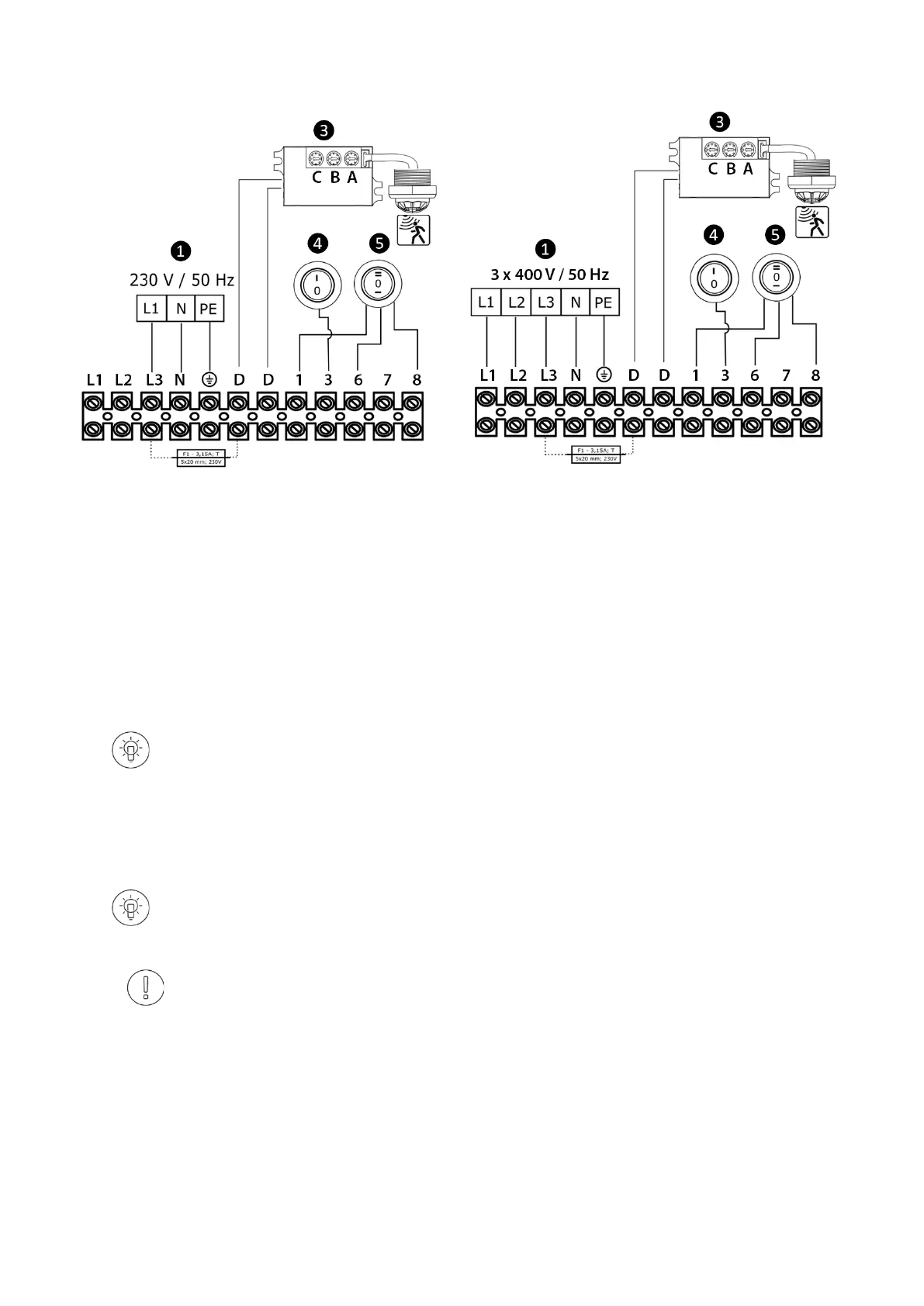
13. BUILT-IN CONTROL – CONNECTION DIAGRAM SLIM E
PIC. 13.1 POWER SUPPLY 1N
~
230V/50 Hz
PIC. 13.2 POWER SUPPLY 3N
~
400V/50 Hz
❶ Power supply:
1N ~ 230V/50Hz:
• SLIM E-100 (OMY min.3x1,5 mm
2
; Protection B10)
• SLIM E-150 (OMY min.3x1,5 mm
2
; Protection B16)
• SLIM E-200 (OMY min.3x2,5 mm
2
; Protection B20)
3N ~ 400V/50Hz:
• SLIM E-100 (OMY min.5x2,5 mm
2
; Protection B10)
• SLIM E-150 (OMY min.5x2,5 mm
2
; Protection B16)
• SLIM E-200 (OMY min.5x4,0 mm
2
; Protection B20)
- The maximum outer diameter of the cable sleeve is 14.0 mm;
- The minimum outer diameter of cable sleeve is 4.0 mm;
- Maximum wire diameter 4,0 mm
2
.
❸ Motion sensor; to omit/bypass the motion sensor; disconnect and insulate / secure wires from connectors D; D, a cable jumper
(OMY min. 1x1,0 mm
2
) or a door sensor (OMY min. 2x1,0 mm
2
) should be connected in this place;
❹ Heating switch (
heating elements ON ,
O – heating elements OFF);
❺ Fan step switch (
1st fan step,
O – device OFF, I I – 3rd
fan step
To connect the 2nd fan step, connect the cable from the 6th connector to the 7th connector. In this case,
the I position on the switch will mean SWITCHING ON the 2nd fan step.
Each time the curtain is turned on by a motion sensor, it operates for a set time (10 s by default), unless
motion is detected in the area covered by the sensor.
In the event of a hazard arising from the unintentional reset of the thermal switch, this equipment should
not be powered by an external connecting device, such as a time switch, or a disconnector connected to
the circuit, which is regularly switched OFF and ON during use.

 Loading...