EasyManua.ls Logo

Flowmaster FORCE II - User Manual

Flowmaster FORCE II
2 pages
Print Icon
To Next Page IconTo Next Page
Loading...
Installation Instructions for
SYSTEM #817517
1997-2004 CHEVROLET C5 CORVETTE
5.7L V8 ENGINE
409S® Stainless Steel
10/05/11
1)
Raise the vehicle up on a hoist or rack to working height. If you do not have access to a hoist or rack,
raise the vehicle and support securely with jack stands.
2)
At the front of each of the muffler/over axle pipe assembly there is a two bolt
flange. Using a 15mm wrench loosen the nuts and remove the bolts from these
connections. Retain the hardware; it will be used for the installation of the
Flowmaster system.
3)
Using a 13mm socket and extension, remove the two nuts that secure the
rear muffler rubber hanger to the frame. This will allow the muffler to be removed
from the car. Lower the rear of the muffler and slide the over-axle pipe from over the
rear end. Slide the rubber hangers off of the stock mufflers and onto the bracket
located on the Flowmaster muffler.
4)
Place the right over-axle pipe #16377S over the rear end and connect to the
factory flange. Replace the hardware removed in step 2 and tighten securely. Repeat
this step with the left over-axle pipe #16378S.
5) Place a supplied 2.50” clamp onto the inlet of muffler 8525802-R and slide it
over the end of the right over-axle pipe #16377S. Rotate the muffler up so that the
rubber hanger fits into place over the studs. Install the two nuts and tighten securely.
Repeat these steps for the left side muffler #8525802-L and over-axle pipe #16378S.
6)
Adjust the position of both mufflers to provide a satisfactory fit and tighten the muffler clamps securely.
The clamps should be placed with the bolts and hardware oriented to minimize visibility.
7) For a cleaner appearance and more secure installation, we highly recommend welding all slip-fit
connections.
Pg 1 of 2 Technical Support (800) 544-4761
Question and Answer IconNeed help?

Do you have a question about the Flowmaster FORCE II and is the answer not in the manual?

Summary

Exhaust System Installation Procedure

Vehicle Preparation

Raise the vehicle on a hoist or rack or support securely with jack stands.

Stock Exhaust Removal

Remove front flange bolts and rear muffler hanger nuts to detach the stock muffler assembly.

New Exhaust System Installation

Install over-axle pipes and mufflers using supplied clamps and hardware, then adjust and tighten.

Final Recommendations

Ensure proper fit, tighten clamps securely, and consider welding slip-fit connections for enhanced durability.

Overview

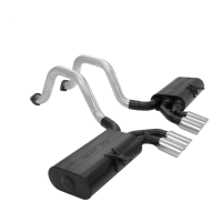
This document provides installation instructions and a packing list for the Flowmaster Force II exhaust system, specifically model #817517, designed for 1997-2004 Chevrolet C5 Corvette vehicles with a 5.7L V8 engine.

The Flowmaster Force II exhaust system is designed to replace the factory exhaust components, offering an upgrade in performance and sound. While the document does not explicitly detail the "function description" beyond being an exhaust system, Flowmaster's Force II series is generally known for delivering a moderate to aggressive exhaust tone, improved exhaust flow, and enhanced engine performance compared to stock systems. The "Force II" designation typically indicates a system that provides a noticeable but not overly aggressive sound, suitable for daily driving while still offering a performance benefit. The system is constructed from 409S stainless steel, as indicated by "409S Stainless Steel" on the cover page, which suggests good durability and corrosion resistance.

Important Technical Specifications:

  • System Model: #817517
  • Vehicle Compatibility: 1997-2004 Chevrolet C5 Corvette, 5.7L V8 Engine
  • Material: 409S Stainless Steel (as indicated by "409S Stainless Steel" on the cover)
  • Components (Packing List):
    • Right Over-Axle Assembly: Part #16377S (Quantity: 1)
    • Left Over-Axle Assembly: Part #16378S (Quantity: 1)
    • Right Muffler Assembly: Part #8525802-R (Quantity: 1)
    • Left Muffler Assembly: Part #8525802-L (Quantity: 1)
    • Parts Kit: Part #PK596 (Quantity: 1)
    • 2½" Band Clamp: Part #MC250BS (Quantity: 2)
    • Gaskets: Part #GA109 (Quantity: 2)
  • Clamp Size: 2½" (for connecting mufflers to over-axle pipes)

Usage Features:

The installation process is detailed step-by-step, making it accessible for individuals with mechanical experience or professional installers.

  1. Vehicle Preparation: The first step involves raising the vehicle to a working height using a hoist, rack, or jack stands, emphasizing safety.
  2. Disassembly of Stock System:
    • The existing muffler/over-axle pipe assemblies are disconnected from the factory flange using a 15mm wrench to remove two bolts and nuts. The original hardware is to be retained for reuse.
    • The rear muffler rubber hangers are detached from the frame by removing two nuts with a 13mm socket and extension.
    • The stock mufflers are then removed by lowering the rear and sliding the over-axle pipes from over the rear end.
    • The rubber hangers are transferred from the stock mufflers to the brackets on the new Flowmaster mufflers.
  3. Installation of Flowmaster System:
    • The right over-axle pipe (#16377S) is positioned over the rear end and connected to the factory flange using the retained hardware from step 2. This connection is then securely tightened. The same process is repeated for the left over-axle pipe (#16378S).
    • A supplied 2.50" band clamp (#MC250BS) is placed onto the inlet of the right muffler (#8525802-R) and slid over the end of the right over-axle pipe (#16377S).
    • The muffler is rotated so that its rubber hanger aligns with and fits onto the existing studs on the vehicle's frame. The two nuts are then installed and tightened securely.
    • These steps are mirrored for the left side, installing the left muffler (#8525802-L) onto the left over-axle pipe (#16378S).
  4. Adjustment and Final Tightening:
    • Both mufflers are adjusted to achieve a satisfactory fit, ensuring proper alignment and clearance.
    • The muffler clamps are then securely tightened. The instructions specify orienting the bolts and hardware of the clamps to minimize their visibility, contributing to a cleaner aesthetic.
  5. Optional Welding: For enhanced durability, a cleaner appearance, and a more secure installation, the manufacturer highly recommends welding all slip-fit connections. This suggests that while the clamps provide a secure connection, welding offers a permanent and potentially more robust solution, reducing the risk of leaks or loosening over time.

The system includes gaskets (GA109) for the flange connections, ensuring a leak-free seal at the interface with the existing exhaust components. The use of band clamps for muffler connections is a common practice, allowing for some adjustability during installation and providing a good seal when tightened correctly.

Maintenance Features:

The document does not explicitly detail ongoing maintenance features for the exhaust system itself, as exhaust systems generally require minimal routine maintenance once installed. However, the choice of 409S stainless steel for construction implies a degree of corrosion resistance, which contributes to the longevity of the system and reduces the need for frequent replacement due to rust.

  • Corrosion Resistance: 409S stainless steel is a ferritic stainless steel known for its good corrosion resistance, particularly in exhaust environments where it is exposed to heat, moisture, and corrosive gases. This material choice helps in extending the lifespan of the exhaust system compared to less resistant materials like mild steel.
  • Secure Connections: The recommendation for welding slip-fit connections, while optional, highlights a method to enhance the long-term integrity of the system, potentially reducing the need for re-tightening clamps or addressing exhaust leaks over time. If not welded, periodic inspection of the clamp tightness might be a good practice to ensure continued secure connections.
  • Component Replacement: The packing list clearly identifies individual components (over-axle pipes, mufflers, clamps, gaskets) with specific part numbers. This modular design could facilitate the replacement of individual damaged or worn components if necessary, rather than requiring the replacement of the entire system. For example, if a muffler were to be damaged, it could theoretically be replaced using its specific part number (e.g., 8525802-R or 8525802-L).

In summary, the Flowmaster Force II system #817517 for the C5 Corvette is a performance-oriented exhaust upgrade made from durable 409S stainless steel, designed for a straightforward installation process that can be further enhanced by optional welding for maximum security and longevity. It aims to provide improved exhaust flow and a characteristic Flowmaster sound.

Flowmaster FORCE II Specifications

General IconGeneral
BrandFlowmaster
ModelFORCE II
CategoryAutomobile Accessories
LanguageEnglish