7 Instruction Manual
General
The β-meter display/signal converter allows a fast response time for the sensors ≤150NB.
This is achieved by automatically selecting higher coil frequencies permitting faster update
times for flow calculations.
These features allow batching of small volumes and ensure an acceptable accuracy.
Size 50Hz Power Supply 60Hz Power Supply
Coil Frequency Update Time Coil Frequency Update Time
10-25mm 12.5Hz 80ms 15.0Hz 66.66ms
26-150mm 6.25Hz 160ms 7.5Hz 133.33ms
151-800mm /
Insertion Mag
3.125Hz 320ms 3.75Hz 266.66ms
Output Functions
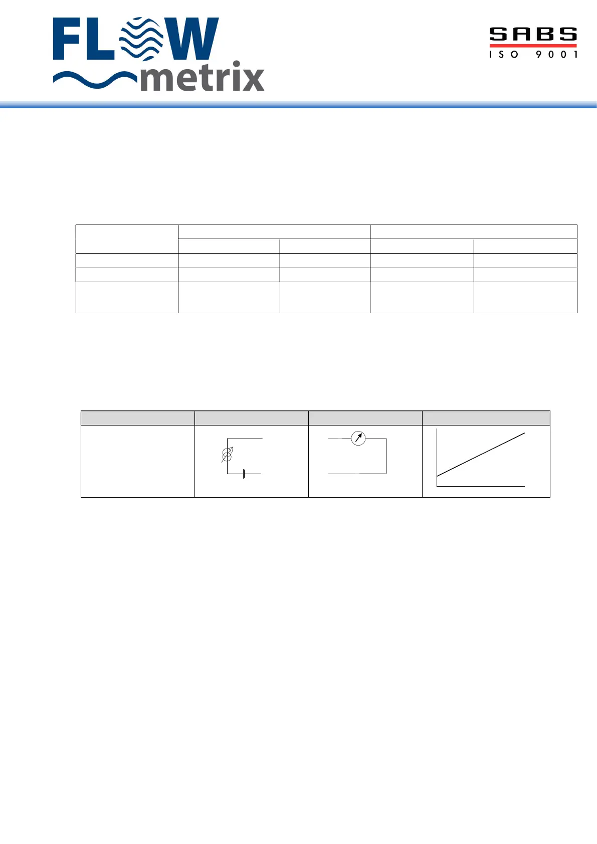
4-20mA
The 4 – 20mA output signal is proportional to the flow rate. 4mA = 0 flow rate. The full-scale
value (i.e. 20mA) is the flow rate figure programmed into menu item M1_2.
Flow rate
Current Loop
(Active)
Open Collector Transistor
The open collector transistor outputs OCT1, OCT2, and OCT3 are individually programmable
for any of the following functions.
Forward flow totaliser pulse output, Batch control function, No coil current alarm, Empty pipe
alarm, Pulse output alarm (i.e. frequency > 1250Hz), Reverse flow alarm, Low flow rate alarm,
High flow rate alarm.
The output signal can be wired as:
Open collector output between the PULS+ and PULS- terminal when the switch is OFF.
24V binary signal available between the PULS+ and PULS- terminal when the switch is ON
Pulse Output
Menu option M2_7 volume/pulse is used to determine the pulse frequency
The pulse width is determined by the M2_8 puls-width programmed unless –
1. pulse frequency exceeds the coil frequency or
2. frequency cannot accommodate the programmed pulse width
then output will change to pulses with equal mark space ratio.
It is important to remember that the flow sensor size determines the coil’s frequency.
+
4-20mA-
4-20mA+
+
mA
R
LOAD < 600Ω
mA
%
0
20
100
4
 Loading...