JetFlow Relay
User Instruction – AIIOM000287
10
NOTE: To meet the requirements of captured vented air,
air must be captured from the JetFlow vent ports and the
positioner vent port. Refer to the Logix™ 3800 Digital
Positioner FCD LGENIM0112 for instructions to capture
vented positioner air.
To capture vented air from the JetFlow remove the JetFlow
vent covers and connect the necessary tubing/piping to the
ports.
6 OPERATION - HOW IT WORKS
6.1 Basic Operation
The JetFlow is a spool and block pneumatic relay designed
to work in conjunction with the Logix 3820 digital positioner to
make large actuator position changes within seconds.
The Logix 3820 positioner receives 4-20 mA input position
signals through HART communication protocol. The
positioner translates the electrical position control signals into
pneumatic signals, which activate the JetFlow, to relay
supply air to the actuator, causing it to move to command
position.
NOTE: A solenoid may be added to the system as a
secondary failsafe measure. The solenoid can be connected
in series along the pneumatic control signal from the
positioner port A to the JetFlow diaphragm. The solenoid
must be energized for the JetFlow to operate.
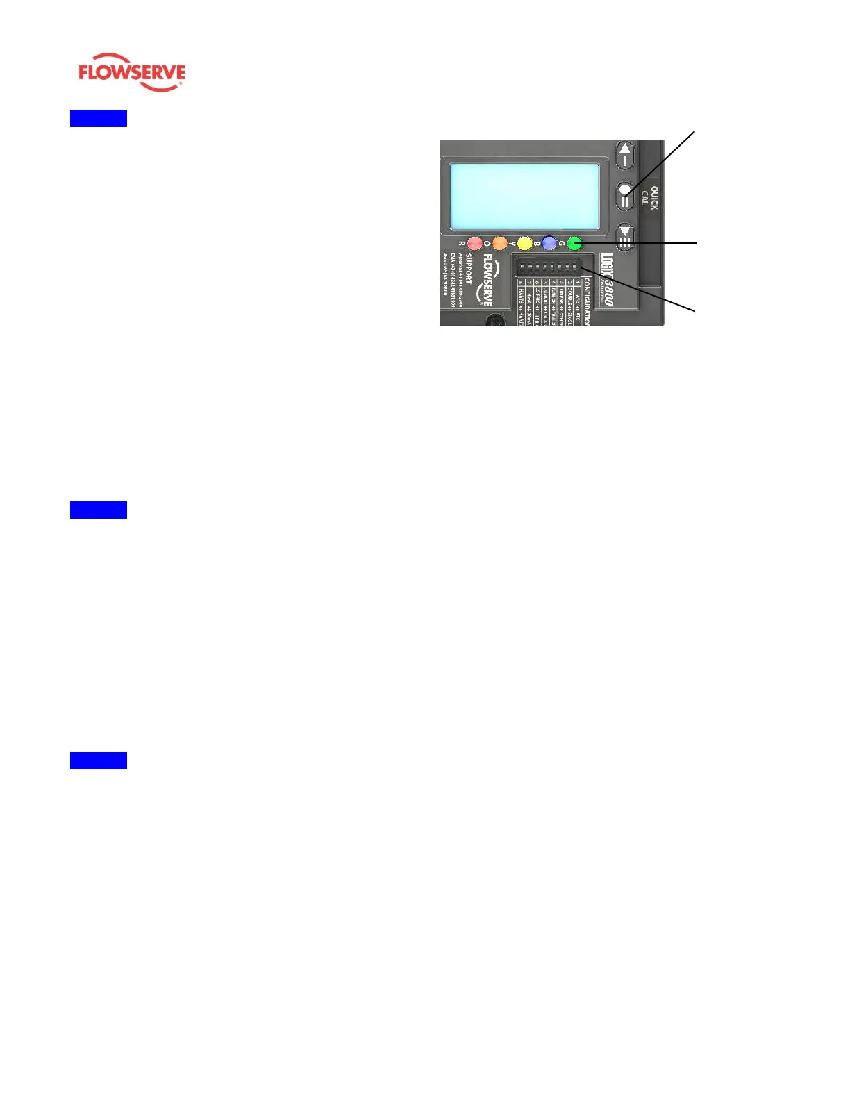
7 OPERATION – DIP SWITCH
CONFIGURATION
Before placing the unit in service verify the DIP Switches are
set to the desired control options. The functionality of the DIP
Switches is the same for the Logix 3800JF and Logix 3800,
see Figure 6: Local User Interface. However, certain DIP
Switches are required to be set specifically for use with the
JetFlow relay.
NOTE: DIP Switch settings do not take effect immediately
but are activated by performing a Stroke Calibration
(pressing the “QUICK-CAL” button for 3 seconds). DIP switch
settings may be edited from the DTM or Handheld at any
time.
Figure 6: Local User Interface
7.1 Actuator Switch
(DOUBLE◄►SINGLE)
The actuator switch must be set to Double to work correctly
with the JetFlow relay.
Refer to Logix™ 3800 Digital Positioner FCD LGENIM0112
for more information about setting the positioner DIP
switches
8 OPERATION -USER INTERFACE
8.1 Current Alarm Status
The current alarm status area of the positioner LCD will
display the highest priority alarm, warning, alert, or status
indication of the JetFlow or positioner. This matches the code
indicated by the flashing LEDs
8.2 Status Icons
A JetFlow status icon, represented as a JF, will display on
the positioner LCD screen. The status icon indicates a
JetFlow is connected and recognized by the positioner and
that the positioner is operating JetFlow control software. See
Table 1: Status Icon for an illustration of the JetFlow status
icon.