32
Tools
Screwdriver (5.5/100)
Attention
To provide sufficient ventilation, ensure a minimum spacing of 20 mm between
adjacent units.
Installation
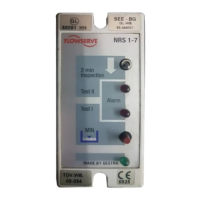
NRS 17
On supporting rail (with mounting clip)
1. Clip level switch onto supporting rail.
2. Loosen cover screws
1 and unplug cover 3 from its base 2.
3. Select cable entry
5 and remove corresponding seal.
On mounting panel
1. Loosen cover screws
2 and unplug cover 3 from its base 2.
2. Unscrew mounting clip
4.
3. Drill the hole
7 marked in the base to ∅ 4.3 mm.
4. Select cable entry 5 / 6 and remove corresponding seal.
5. Fasten base with two screws M4 onto mounting panel.
§ Cover screws
$ Base
% Cover
& Mounting clip
/ Cable entry (flexible)
( Cable entry (housing)
) Hole d = 4.3 mm
= Supporting rail 35 x 15 mm to DIN EN 50022
Key
EN