34
Wiring
NRS 17
Cable required for wiring to the electrode: fourcore screened cable, e. g. IY(St)Y 2 x 2 x 0.8 or
LIYCY 4 x 0.5².
Max. cable length 100 m with a conductivity from 10 µS/cm.
Max. cable length 30 m with a conductivity from 0.5 µS/cm.
Max. cable length 15 m with a conductivity from 0.5 µS/cm when used in conjunction with inverter
URN 1 (24 V d. c.)
Tools
Screwdriver for slotted screws, size 2.5, completely insulated according to VDE 06801.
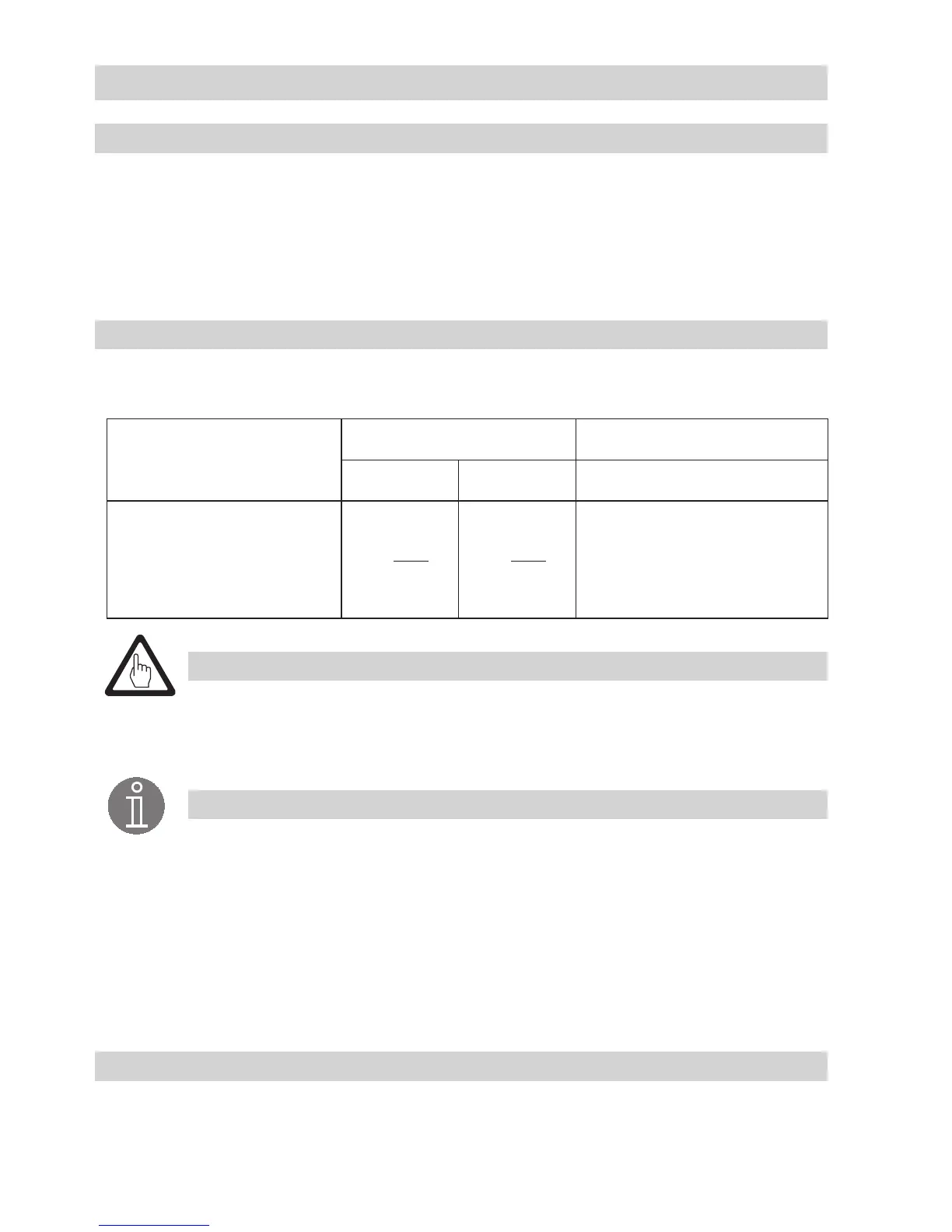
Voltage table
Use this voltage table as reference when checking the level electrode for malfunction or submersion.
Take the wiring diagram (see Fig. 10, Fig. 11) into account.
U
12
U
1⊥
U
2⊥
Submerged Exposed Malfunction (submerged/alarm)
10 V
eff
0.5 µS/cm,
C = 0.13 cm
1
2 V
eff
10 µS/cm,
C = 0.3 cm
1
<
U
12
2
≥
U
12
2
≤ U
1
⊥
Attention
To protect the switching contacts provide the circuit with a 2.5 A slowblow fuse or
according to TRD regulations (1.0 A for 72 hrs operation).
The screen must not make any other electrical contact.
Note
The selfchecking routine of the NRS 17 reduces U
2
⊥
every 40 sec. considerably,
even down to 0 volt.
Connect screen only to terminal 8 of the level switch.
The sensitivity is indicated on the name plate.
The rated voltage is indicated on the name plate.
When switching off inductive loads, voltage spikes are produced that may impair
the operation of control and measuring systems. Inductive loads should therefore be
provided with commercial arc suppressor RC combinations, e. g. 0.1 µF / 100 Ω.
EN