INSTALLATION
AND
OPERATION
Related Operations;
Relative Function
2-35.
REMOTE OPERATION (IEEE-488 INTERFACE)
The following paragraphs describe how to operate
the Generator using the IEEE-488
Interface
(referred to as remote operation). The interface allows the operator
to program the
Generator
and operate instrument functions via the IEEE-488
bus (with the exception of
the front panel
POWER
switch and
the rear
panel REF INT/EXT switch).
The IEEE-488 Interface
also
provides additional programming features not accessible
from the front panel.
The rest of this section is divided into two parts:
the first part describes how to set
up the
Generator for
operation
on the IEEE-488 bus and gives some ty pical programming
examples.
The first part also includes a complete list of the programming
commands recognized
by
the
Generator
software.
The
second part describes the implementation
of the IEEE-488 Interface and programming
features that are accessible only from the IEEE-488 Interface. The
second part also includes
typical timing data, provided as an aid to system programmers.
This information can assist in
writing programs that have greater speed and efficiency.
The Generator
can be used with any IEEE-488 controller in the normal addressed mode. The
following two additional
modes are available for operation without a
controller:
Listen-only
mode
Talk-only mode
In the
listen-only
mode, the Generator responds
to all data messages
on the IEEE-488
bus. In
the talk-only mode, the Generator
sends commands
on the IEEE-488 bus to program
another
606xA Generator
(or a 607xA with some restrictions).
2-36.
Setting
Up
the IEEE-488
Interface
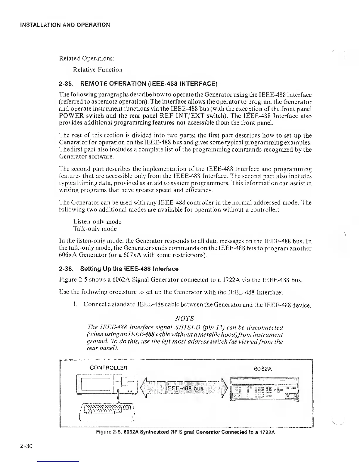
Figure
2-5
shows a 6062A Signal Generator
connected to
a 1722A via the IEEE-488
bus.
Use the following procedure
to set up the Generator
with the IEEE-488
Interface:
1 . Connect a standard
IEEE-488 cable between
the Generator
and the
IEEE-488
device.
NOTE
The IEEE-488 Interface signal
SHIELD (pin
12)
can
be
disconnected
(when
using an IEEE-488
cable
without
a metallic
hood)
from instrument
ground. To
do this, use the
left
most
address switch (as viewed
from
the
rear panel).
Figure
2-5.
6082A Synthesized
RF Signal Generator Connected
to a
1722A
2-30
 Loading...