PV350 English Instruction Sheet
Page 6
2. Connect the pressure regulator to the nitrogen bottle and the
reference pressure gauge to the pressure regulator. The nitrogen
bottle must have >750 psi.
3. Verify the condition of the battery and if necessary, replace the
battery. (Refer to Figure 2.)
4. Remove the top cover of the module and connect it to the mV input
of the DMM. Set the scale to measure 500 mV (0.1 mV resolution).
5. Turn on the PV350 and allow it to warm up for two minutes.
6. Set the PV350 to the psi range.
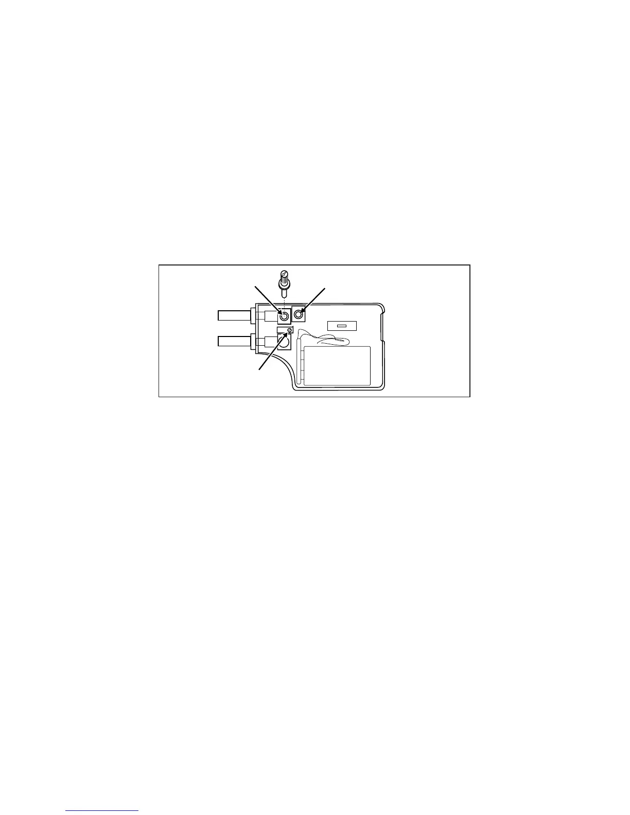
7. Center the ZERO potentiometer, R3 (see Figure 5). Remove the
knob from R3 and insert it into R4 (the coarse zero adjustment).
With no pressure applied, set the reading to 0 mV ±0.3 mV. Insert
the knob back into R3, and adjust the final reading to 0.0 mV,
±0.1 mV.
R4
R3
R16
Figure 5. Calibration Adjustment Points
8. Connect the sensor to the pressure reference and nitrogen bottle
pressure calibration system.
9. Adjust the pressure regulator to about 250 psi. The readings on the
reference pressure gauge and the reading from the PV350 should
agree within ±0.1 % of the point, ±-0.3 psi: approximately ±0.6 mV
or ±0.6 psi. Adjust R16 as necessary.
10. Adjust the pressure regulator to about 350 psi. The readings on the
reference pressure gauge and the PV350 should agree within
±0.1 % of the point, ±0.3 psi: approximately ±0.7 mV or ±0.7 psi. If
necessary, adjust R16 to bring the reading into specification and
recheck the 250 psi point. It may be necessary to repeat steps 9 and
10 until both points are within specification.
11. Reduce pressure to zero and switch the module OFF.
How to Verify Calibration
1. Connect the sensor (transducer) to a pressure calibration standard,
and plug the module into the DMM.
2. Be sure the system is vented, then zero the module.
3. Enter the pressure settings shown in Table 2 and check for the
indicated readings