50 / 84 Attachment FLUXTRONIC Automatic Mode
4 Technical data
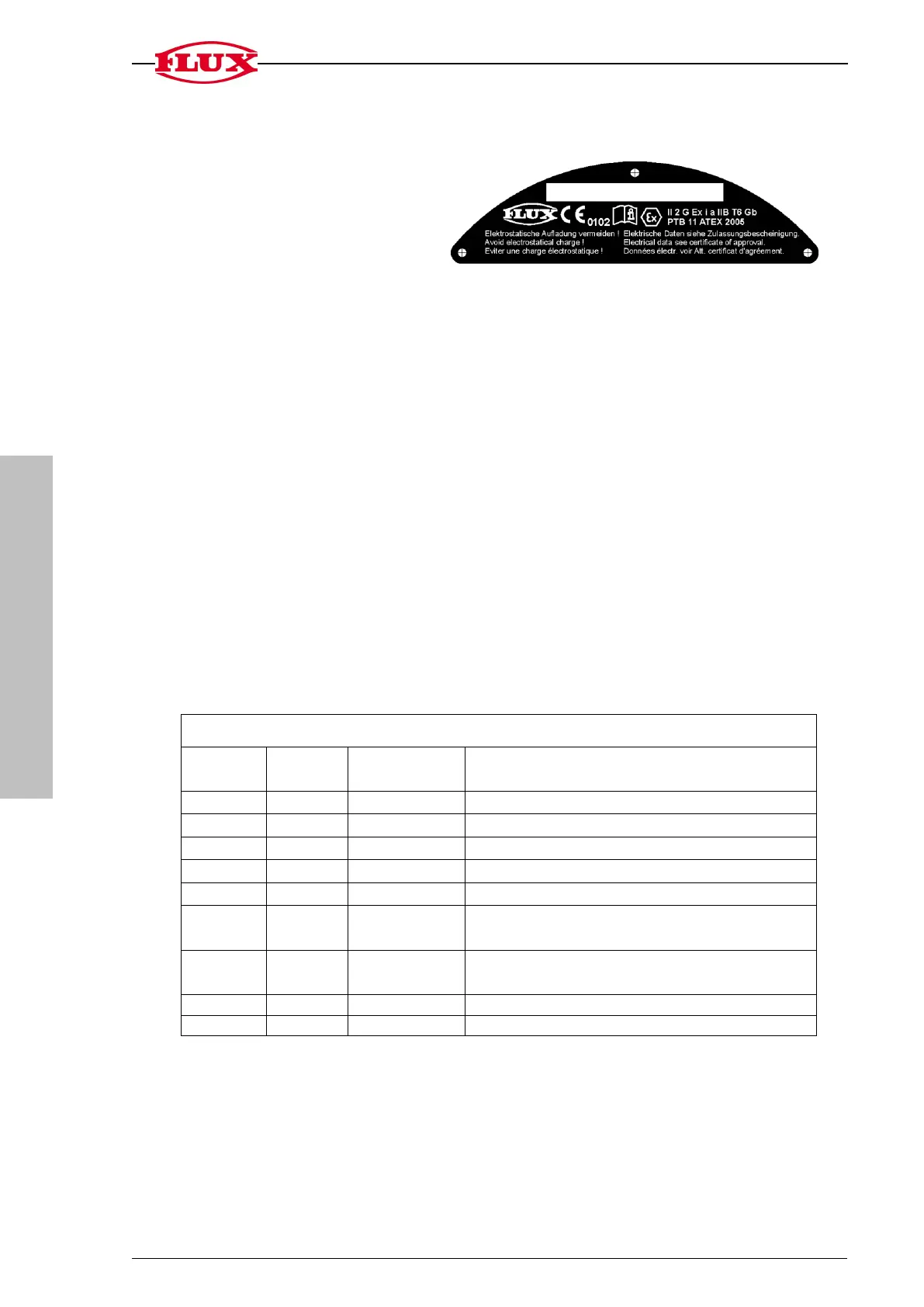
Explosion protection marking:
II 2 G Ex i a IIB T6 Gb
PTB 11 ATEX 2005
Electrical Data see Certificate
of Acceptance
Storage temperature -25°C up to max. +70°C
Surrounding temperature -20°C* up to max. +40°C
*At temperatures below 0°C the LCD display is slowed down.
Material: Electronic unit housing PP; Display PSU; Panel PP
Battery: Lithium CR 2032
Service life: 1 to 2 years, depending on use
Sensor input: Mechanical contact
Frequency max. 150 Hz with key ratio of 50/50
Pulse output
NAMUR output
A NAMUR isolating amplifier with an input and output transistor is needed to use the
output.
Frequency max. 150 Hz with key ratio of 50/50
Pulse length set with 2 ms regardless of the frequency
OK output
The OK output is switched on for approx. ~ 60 mS following a complete filling process.
*1
When using the input for an external sensor the plug of the integrated sensor has
to be unplugged.
*2
Attention! Not permitted in explosion-proof areas
In case of an external power supply use PIN 8 Minus and PIN 9 Plus.
Assignment of the 9-pin contact strip
NAMUR Exit pulse redirection
NAMUR exit switch signal S2 (pre-signal)
NAMUR exit switch signal S1 (main signal)
Input external pulses (Reed switch)
It is switched with +3V (9).
Input external Start/Stop (key input)
It is switched with +3V (9).
Minus connection (for NAMUR exits)
Plus connection (for entries 6 and 7)
 Loading...