2
Connecting the charger
Connecting packs with a Cellpro connector
Connect packs as shown in this diagram:
Connect to 10–16 VDC
(e.g., gel cell or power supply)
Optional connection to PC
using FMA FUIM2
or FUIM3 cable
Cellpro Multi4 Charger
From pack being charged:
Node Connector*
(for balanced or unbalanced
charging)
or
Power Connector*
(for unbalanced charging)
*may require adapter
Mode
Button
Data display
CAUTION: When two LiPo/Li-Ion/A123 packs are connected in series, do not connect
them to two separate chargers that are wired to a single power source. This sets up the
condition in which the series-connected packs are being charged in parallel (the power
source provides a common ground). The Multi4 Charger contains protective circuitry
that prevents it from starting a charge when it detects this situation. However, one
or both chargers, as well as the packs, could be damaged. This condition can be
avoided if the chargers are driven from two unconnected power sources (e.g., two lead
acid batteries). For safest charging of series-connected packs, disconnect the packs
from each other before connecting them to chargers.
Connecting non-Cellpro packs
FMA Direct offers plug-and-play adapters for charging LiPo/Li-Ion/A123 packs equipped
with node connectors made by other vendors. Check the Cellpro section at www.fmadirect.
com for the latest adapters.
If an adapter isn’t available for the pack you want to charge, or if the pack doesn’t have a
node connector, the FMA CPBP7 LiPo Pack Node Connector cable assembly will make the
pack compatible with the Cellpro Multi4 Charger. The diagrams below show how the Node
Connector attaches to packs of various confi gurations. Additional assembly information is
provided with the Node Connector.
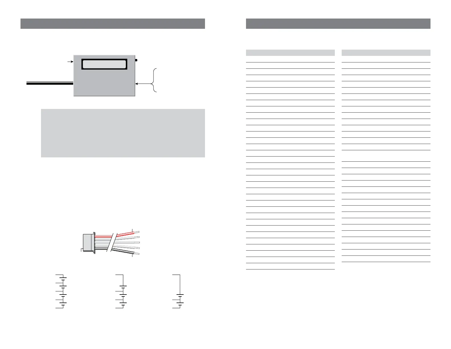
Pin 1
FMA CPBP7 LiPo Pack
Node Connector
Red
Black
Pack positive
Node 3
Node 2
Node 1
Pack negative
Cell 4
+
–
Cell 3
+
–
Pack positive
(red), 14.8V*
Pack negative
(blk), 0V
Node 3, 11.1V*
Cell 2
+
–
Node 2, 7.4V*
4s Pack
Cell 1
+
–
Node 1, 3.7V*
Cell 3
+
–
Cell 2
+
–
Node 2, 7.4V*
3s Pack
Cell 1
+
–
Node 1, 3.7V*
Pack postive
(red), 7.4V*
Pack negative
(blk), 0V
Pack postive
(red), 11.1V*
Pack negative
(blk), 0V
Cell 2
+
–
2s Pack
Cell 1
+
–
Node 1, 3.7V*
* Nominal voltage with respect to pack negative.
19
Troubleshooting
Operating errors appear as safety codes in the display. If possible, correct the error. If errors
continue, contact FMA Customer Service.
Code Cause
1 Increase Supply
2 Supply <10 Volts
3 Supply >16 Volts
4 Supply Unstable
5 Prset not for 4S
6 Bad Preset Versn
7 Reduce NiCd Amps
8 Series Chrgrs?
9 P. Library Empty
10 Low Voltage Cell
11 Preset is Hidden
12 Reverse Polarity
13 Preset is Empty
14 MODE not Pressed
15 System Softstart
16 Preset is Locked
17 Ch1 No Add Up
18 Max Cells Error
19 No Pack
20 Bad Cell Count
21 Bad P. Ram Check
22 Cells Exceeded
23 Un-Bal. Only
24 Charge Timeout
25 Cell Cnt Changed
26 NiCd Detected
27 Cells no Correct
28 Cell OverVoltage
78 High Voltage When Off
79 CH1 Cells Out of Range
88 Checkpack1 Cell V Out of Range
90 Unknown Screen Number
92 Mux Number Error
93 Calibration Checksum Bad
Code Cause
94 Bad EEPROM Write
95 Bypass Overvolt
96 PWM Ratio Too High
97 Bad FET Supply Voltage
98 Charger Overcurrent
99 Bad Mode Number
100 Temp out of Rnge
105 Preset not validated
106 Preset number out of range
107 Charge Timeout out of range
108 Preset loaded while charging
109 Charge Termination Unknown
111 Preset Cell OverVolts too High
112 Options Checksum is BAD
113 Charge PWM not regulating
114 Bad Preset Flash Checksum while
running
115 Bad Preset Flash Checksum on Start
116 Bad Preset Ram Checksum on Start
117 Bad Segment Checksum on Start
118 Bad Segment Checksum while running
120 Lithium Cell Count not Verifi ed
121 Shunt FET off while CHG/DSCH
122 Unknown Chemistry
123 No Charge Screens to Show
124 Bad Run Screen Number
125 Cell Count is Zero
126 Discharge Mode not set to Balancer
127 Discharge Mode Timeout
128 Peek Detect set past 15 min
129 NiCd Chem must use FallBack
130 Lith Chem must not use FallBack
131 Oscillator Calibration Erased
 Loading...