Do you have a question about the FMX TD400 Series and is the answer not in the manual?
Covers essential steps before powering the AC Drive, including terminal wiring.
Details critical wiring practices, grounding, and safety warnings for installation.
Provides crucial guidelines and warnings to follow before operating the AC Drive.
Explains cautions and prerequisites for performing the motor's rotational auto-tuning process.
Covers important warnings and cautions related to operating the AC Drive and motor.
Outlines safety precautions and procedures for maintenance, inspection, and component replacement.
Provides guidelines for the safe and environmentally responsible disposal of the AC Drive unit.
Details UL standards, compliance requirements, installation area, and wiring terminal specifications.
Explains how to interpret the AC Drive's main nameplate data for identification and specifications.
Provides detailed specifications for wire gauge, terminal torque, circuit protection, and fuse ratings for different frame sizes.
Lists detailed electrical and mechanical specifications for various AC Drive models across different voltage classes.
Outlines general specifications including control modes, frequency, run modes, main control features, display, protective functions, and communication.
Provides detailed physical dimensions and mounting specifications for Frame 1 AC Drives.
Details the environmental conditions required for proper AC Drive operation and lifespan, including protection and installation site.
Provides guidance on installing the AC Drive, ensuring adequate air circulation for cooling and heat dissipation.
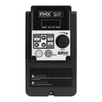
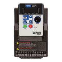
Illustrates the external components and layout of AC Drive frames for identification.
Highlights important warning information that must be read and understood before installing the AC Drive.
Details the procedure for safely removing the front cover to access wiring terminals for connections.
Covers safety precautions and guidelines for wiring peripheral power devices to the AC Drive.
Illustrates a typical AC Drive system diagram, including power supply, circuit protection, and components.
Provides a general wiring diagram showing connections for digital inputs, analog inputs, outputs, and communication.
Details the functions and signal levels of control circuit terminals and the purpose of various jumpers.
Describes the power terminals, their functions, and provides diagrams for different AC Drive frames.
Explains power input terminal connections, grounding, and provides example power connection diagrams.
Discusses the impact of cable length on voltage drop and provides a formula for calculation.
Provides a table correlating cable length with the recommended carrier frequency setting.
Advises on installing an AC line reactor for high-capacity power sources to improve power factor.
Refers to wire size recommendations and emphasizes the need for proper circuit protection.
Provides guidance on isolating control circuit wiring and using shielded twisted-pair cables.
Explains AC Drive output current derating based on carrier frequency and ambient temperature.
Lists recommended braking resistors and their specifications, including wattage and minimum resistance.
Introduces the AC Drive's LED keypad, including display elements and keys.
Explains the function of each LED indicator and key on the AC Drive's keypad for operation.
Details how characters are displayed on the 7-segment LED display, including letters and numbers.
Provides examples of how various information like parameter codes, current, and voltage are displayed on the LED screen.
Explains the meaning of different states (Off, Illuminated, Flashing) for the Hz/RPM, FWD, REV, and PARAM LEDs.
Illustrates the operation sequence using output frequency and LED indicators for FWD and REV commands.
Guides the user on how to navigate and monitor various drive parameters using the keypad.
Provides a step-by-step example of how to change a parameter setting directly from the keypad.
Lists all parameter groups and their descriptions, along with notes on parameter behavior.
Details basic parameters including control mode selection, motor rotation direction, and run command sources.
Details parameters for V/F control, including V/F curve selection and voltage/frequency settings.
Details parameters for Induction Motors (IM), covering no-load current, rated current, speed, voltage, and power.
Outlines parameters for configuring multi-function digital input terminals for various commands and functions.
Details parameters for configuring analog inputs (AI1, AI2) and analog output (AO) for voltage and current signals.
Lists parameters for setting preset speeds, including frequency values and associated acceleration/deceleration times.
Covers parameters for setting up automatic operation modes, including frequency and time settings for stages.
Details parameters related to starting and stopping the AC Drive, including momentary power loss and fault reset.
Lists parameters for various protection functions like stall prevention, motor overload, and overheat protection.
Covers parameters for communication settings, including station address, baud rate, parity, and stop bits.
Details parameters for PID control, including target value source, feedback source, control mode, and gains.
Lists auxiliary parameters such as direction lock, carrier frequency, and S-curve settings.
Details parameters for monitoring AC Drive status, output current, voltage, heatsink temperature, and PID feedback.
Covers parameters related to AC Drive maintenance, including capacity selection, software version, fault records, and cumulative operation hours.
Details parameters for the built-in PLC function, including timer and counter set values.
Lists parameters for monitoring the status of PLC functions, including current values of timers and counters.
Covers parameters related to the LCD keypad display, including screen monitoring, display units, and engineering units.
Details parameters for automatic motor tuning, including mode selection and motor data entry.
Covers parameters for slip compensation, which adjusts output frequency based on motor load for better speed accuracy.
Details parameters for speed control, including ASR gain, integral time, and speed observer settings.
Outlines parameters for setting positive and negative torque limits in forward and reverse directions.
Details parameters specific to Permanent Magnet (PM) motors, including rated power, current, speed, and tuning.
Provides a table of default and maximum values for parameter 11-01 across different AC Drive models.
Introduces basic commands used in PLC ladder logic, including inputs, outputs, and register definitions.
Illustrates basic command functions like positive differential, normal, set, reset, and P output using ladder logic examples.
Explains various application-specific functions within the PLC, such as counters and timers.
Explains the counter function in PLC, including modes, counter value, preset value, and output logic.
Explains various application-specific functions within the PLC, such as counters and timers.
Details the timer function in PLC, covering timer modes, units, reset functions, and set values.
Explains various application-specific functions within the PLC, such as counters and timers.
Explains the analog comparator function, including modes, input selection, reference values, and comparator output.
Explains various application-specific functions within the PLC, such as counters and timers.
Details the operation control function, covering run direction, speed control, segment frequency, and acceleration/deceleration times.
Explains various application-specific functions within the PLC, such as counters and timers.
Explains the math functions (addition, subtraction, multiplication, division) used in PLC programming with calculation examples.
Introduces Modbus communication protocol and its support for monitoring, control, and troubleshooting the AC Drive.
Introduces Modbus communication protocol and its support for monitoring, control, and troubleshooting the AC Drive.
Describes the network connection for Modbus communication, including wiring and pinouts for RS-485 interface.
Introduces Modbus communication protocol and its support for monitoring, control, and troubleshooting the AC Drive.
Details the data format frame structure for Modbus ASCII communication.
Details the data frame structure for Modbus RTU communication, including node address and function codes.
Introduces Modbus communication protocol and its support for monitoring, control, and troubleshooting the AC Drive.
Explains the Cyclic Redundancy Check (CRC) calculation method for ensuring data integrity in communication.
Introduces Modbus communication protocol and its support for monitoring, control, and troubleshooting the AC Drive.
Lists Modbus registers for command data (read/write) and operation signals, including their addresses and bits.
Introduces Modbus communication protocol and its support for monitoring, control, and troubleshooting the AC Drive.
Provides a table of read-only registers for monitoring AC Drive status, fault codes, and warning messages.
Introduces Modbus communication protocol and its support for monitoring, control, and troubleshooting the AC Drive.
Details the command message structure for reading holding registers using Modbus protocol in ASCII and RTU modes.
Introduces Modbus communication protocol and its support for monitoring, control, and troubleshooting the AC Drive.
Explains the procedure for performing a loop back test to check communication between master/client and AC Drive.
Introduces Modbus communication protocol and its support for monitoring, control, and troubleshooting the AC Drive.
Details the command message structure for writing a single holding register using Modbus protocol.
Introduces Modbus communication protocol and its support for monitoring, control, and troubleshooting the AC Drive.
Details the command message structure for writing multiple holding registers using Modbus protocol.
Introduces Modbus communication protocol and its support for monitoring, control, and troubleshooting the AC Drive.
Provides a comprehensive table mapping Modbus functions, register numbers, and group references for parameters.
Provides an overview of BACnet MS/TP protocol implementation and supported standard objects.
Provides an overview of BACnet MS/TP protocol implementation and supported standard objects.
Lists BACnet objects supported by the AC Drive and their properties, including Analog Input properties.
Introduces AC Drive fault detection, warning messages, and self-diagnosis functions.
Explains how to identify and address faults using the LED display, fault codes, and restart methods.
Provides a structured approach to troubleshooting common AC Drive issues like motor direction, speed regulation, and no-run conditions.
Presents diagnostic flowcharts to help identify and resolve AC Drive issues.
Offers a flowchart for quick troubleshooting of AC Drive faults, guiding through checks and potential solutions.
Presents diagnostic flowcharts to help identify and resolve AC Drive issues.
Provides a flowchart specifically for troubleshooting overcurrent (OC) and overload (OL) errors displayed by the AC Drive.
Presents diagnostic flowcharts to help identify and resolve AC Drive issues.
Offers a flowchart for troubleshooting overvoltage (OV) and undervoltage (UV) conditions detected by the AC Drive.
Presents diagnostic flowcharts to help identify and resolve AC Drive issues.
Provides a flowchart to diagnose and resolve issues when the motor fails to run, covering power, wiring, and operation settings.
Presents diagnostic flowcharts to help identify and resolve AC Drive issues.
Outlines troubleshooting steps for motor overheating issues, considering load, speed, and cooling.
Provides steps to diagnose and resolve problems related to unbalanced motor operation, including vibration and fluctuating load.
Presents a checklist for routine and periodic inspections of the AC Drive, covering environment, grounding, terminals, wiring, and input voltage.
Provides guidelines for performing regular maintenance, including a checklist and insulation test procedures.