7
Cabling
WARNING
If there is a doubt as to your ability to install the amplifier and to cable the system properly, get a Focal
distributor to do it for you.
WARNING
Before you begin the connection phase of set-up, remove the vehicle battery’s negative (-) terminal. (fig. A).
CAUTION
Avoid routing power supply cables close to low-level input cables (RCA), to your car’s radio aerial, or to
sensitive units. High-current power supply cables can cause static/interference that affects audio signals.
CAUTION
Keep cables as short as possible to optimise the system’s set-up performance and to reduce
signal loss.
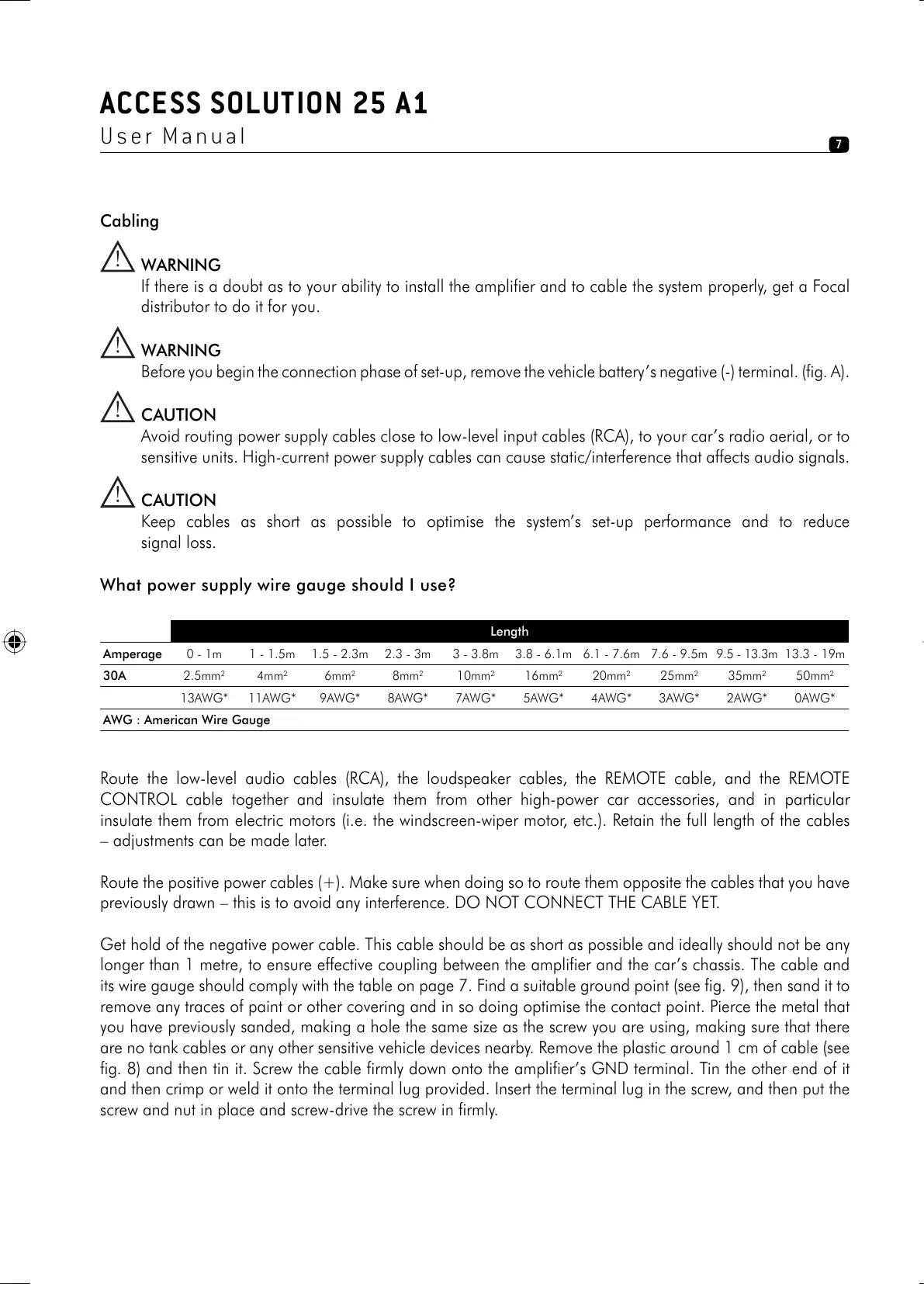
What power supply wire gauge should I use?
Length
Amperage 0 - 1m 1 - 1.5m 1.5 - 2.3m 2.3 - 3m 3 - 3.8m 3.8 - 6.1m 6.1 - 7.6m 7.6 - 9.5m 9.5 - 13.3m 13.3 - 19m
30A 2.5mm
2
4mm
2
6mm
2
8mm
2
10mm
2
16mm
2
20mm
2
25mm
2
35mm
2
50mm
2
13AWG* 11AWG* 9AWG* 8AWG* 7AWG* 5AWG* 4AWG* 3AWG* 2AWG* 0AWG*
AWG : American Wire Gauge
Route the low-level audio cables (RCA), the loudspeaker cables, the REMOTE cable, and the REMOTE
CONTROL cable together and insulate them from other high-power car accessories, and in particular
insulate them from electric motors (i.e. the windscreen-wiper motor, etc.). Retain the full length of the cables
– adjustments can be made later.
Route the positive power cables (+). Make sure when doing so to route them opposite the cables that you have
previously drawn – this is to avoid any interference. DO NOT CONNECT THE CABLE YET.
Get hold of the negative power cable. This cable should be as short as possible and ideally should not be any
longer than 1 metre, to ensure effective coupling between the amplifier and the car’s chassis. The cable and
its wire gauge should comply with the table on page 7. Find a suitable ground point (see fig. 9), then sand it to
remove any traces of paint or other covering and in so doing optimise the contact point. Pierce the metal that
you have previously sanded, making a hole the same size as the screw you are using, making sure that there
are no tank cables or any other sensitive vehicle devices nearby. Remove the plastic around 1 cm of cable (see
fig. 8) and then tin it. Screw the cable firmly down onto the amplifier’s GND terminal. Tin the other end of it
and then crimp or weld it onto the terminal lug provided. Insert the terminal lug in the screw, and then put the
screw and nut in place and screw-drive the screw in firmly.
ACCESS SOLUTION 25 A1
User Manual
notice solution 25 a1.indd 7notice solution 25 a1.indd 7 13/02/07 17:40:0613/02/07 17:40:06