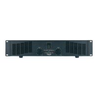
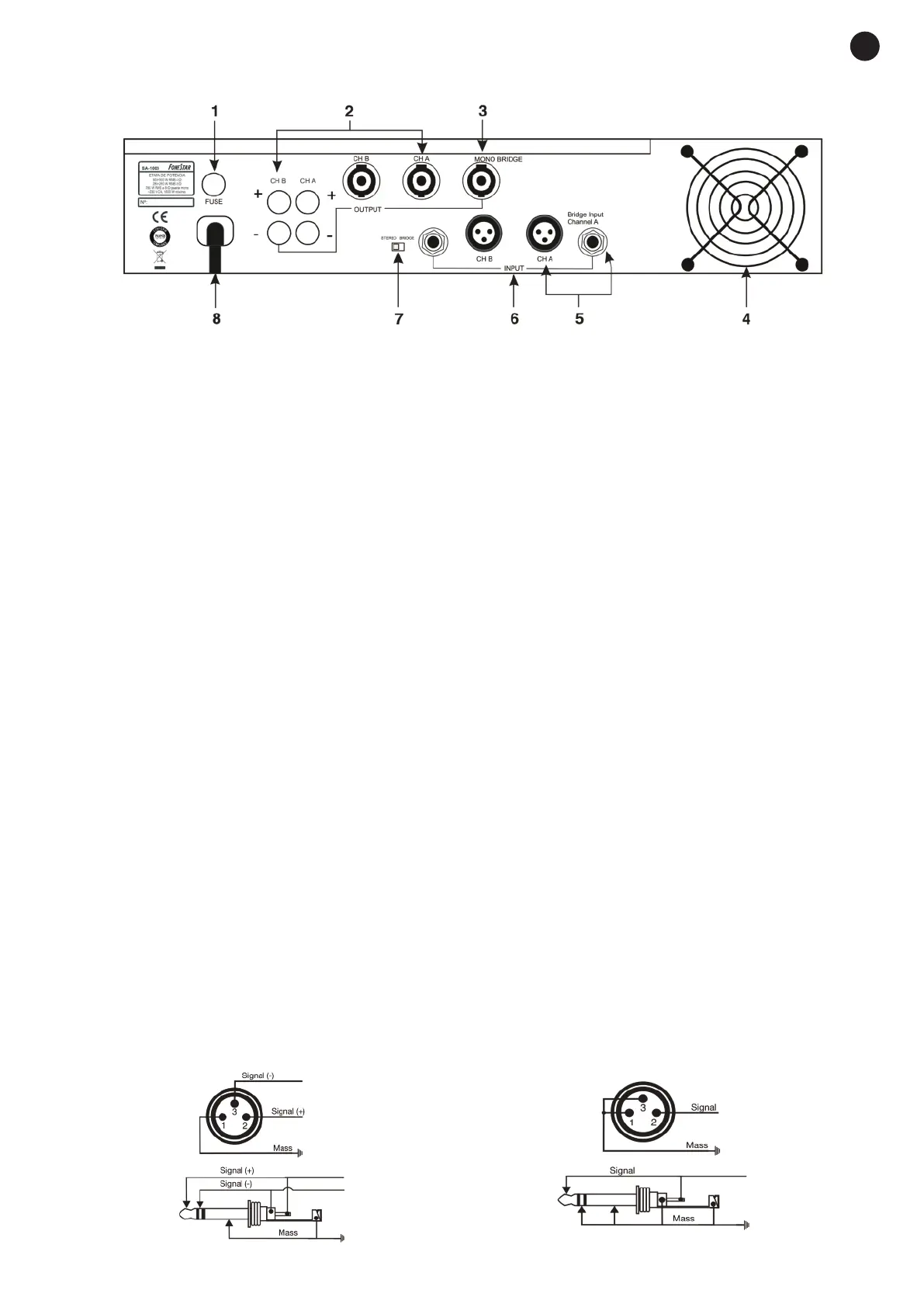
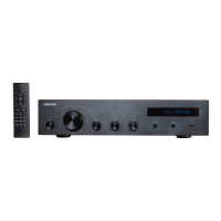
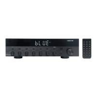
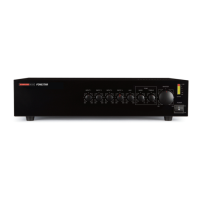
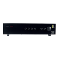
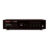
BACK PANEL
1.- FUSE: if you need to change the fuse, change it for one of the same characteristics (shown on the back
panel).
2.- Channels A and B stereo output: speaker output through 4-contact SPEAKON connectors or Red-
Black screw terminals. In the SPEAKON connector connect the 1+ terminal to the positive speaker
terminal and the terminal 1- to the negative speaker terminal.
3.- MONO BRIDGE: bridge output. To activate the mono bridge output the BRIDGE position has to be
selected with the STEREO BRIDGE switch and in this way only the channel A input will be amplified. The
output power in mono bridge will be approximately the sum of the power of the two channels.
The speaker output in mono bridge is only available with the SPEAKON MONO BRIDGE connector. Here
the terminal 1+ must be connected to the positive speaker terminal and the terminal 1- to the negative
speaker terminal. NOTE: Pay attention to the speaker connection. The impedance of the speakers
connected to the output must be the same as the output impedance indicated on the power supply,
never less. Besides, the speaker power must be higher than or the same as the amplifier power to avoid
damaging them both.
4.- Ventilation hole: do not obstruct this hole. The system could overheat.
5.- Input in MONO BRIDGE A channel: in the MONO BRIDGE mode, only the channel A input signal will be
amplified. Use this input exclusively for this.
6.- Stereo input channels A and B: A and B channels stereo signal inputs with XLR or balanced stereo 6.3
mm jack connectors.
7.- STEREO/BRIDGE selector: chooses between stereo mode (channel A and B input and output) or bridge
mode (channel A input and MONO BRIDGE output).
8.- Mains connection: to connect to the mains, 230 V AC, with earth.
PROTECTION: electronic protection prevents the amplifier from suffering damage. The circuits are protected
from high temperatures, DC, short circuit and overload.
In the case of any of the protection circuits being activated, the system will automatically stop working. In
this case, disconnect the system and revise the possible causes. Wait for a while for the system to re-
establish itself (especially if the protection circuit was activated by high temperature) and re-connect the
amplifier.
The connection of the XLR input and jack connectors can be balanced or unbalanced. Make the connection
as in the diagrams below:
- 5-
EN
balanced
mic/line.
unbalanced
mic/line.
XLR and 6.3 mm stereo jack
connectors