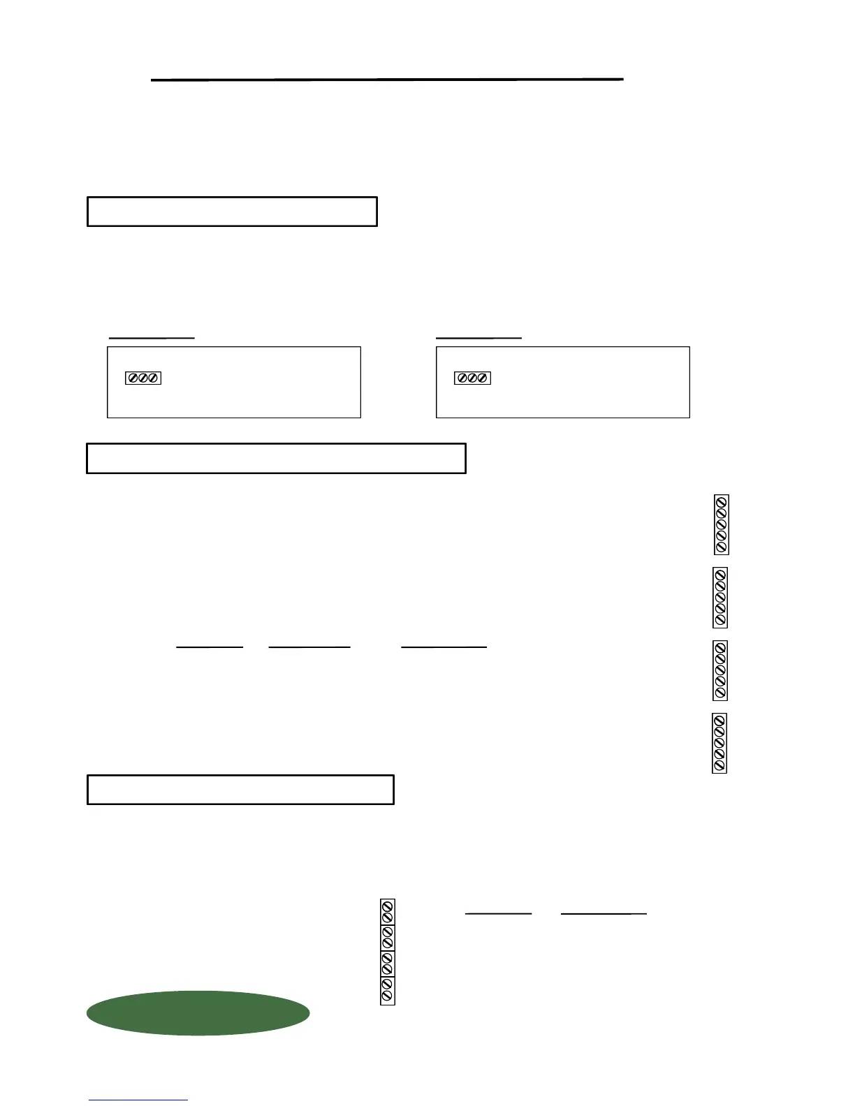
TURN OFF MAIN POWER BEFORE CONNECTING !! Use a clean 110 Volt AC (or 220 Volt, if provided)
power line, connected directly to the main power panel at the facility. DO NOT connect any other inductive
loads, relays, etc. to this power line ! Resulting power surges can damage the electronics !!! Use far left
bottom port and connect per following: (NOTE: Use 1/2" conduit connector)
QUESTIONS ? Help Hotline: 1-800-893-6723
When routing load cell cable into box, use a separate 1/2" cord connector per cable. DO NOT
run load cell cable with any other inductive load or power cables !! Run load cell cable up right
hand side of enclosure and use the cable clamps provided to keep cables from laying on the
PC board. Connect load cell wires per following: (NOTE: Use 1/2" conduit connector)
All connectors have a "PLUG IN" feature to assist in connecting wires. Remove the connector
from the board before attaching wires.
Your 4-20 MA signals are internally powered for up to 900 OHMS each. DO NOT use external loop power.
Run 4-20 MA wiring up the right hand side of enclosure using the cableclamps to keep wires off of PC Board.
(NOTE: Use 1/2" conduit connector). If more than one (1) 4-20 MA signal is used, you may use the same conduit
and connector, but DO NOT run 4-20 MA signals with any other power lines, which carry an inductive load..
+ EXCITATION
- EXCITATION
INDICATOR INSTALLATION & WIRING
ALWAYS SHUT OFF MAIN POWER, AS WELL AS POWER TO ANY AUXILIARY EQUIPMENT
THAT WILL BE INSTALLED IN THIS UNIT, BEFORE OPENING FRONT OF CASE !!
DESCRIPTION
POWER IN
PC BOARD
DO NOT CUT LOAD CELL CABLE !! This may void your warranty!! Your WIZARD 4000
Indicator is shipped with the load cells connected and ready to power up. Should you
need to run the load cell cable through conduit, first unplug the connector from the board,
then disconnect wires, and remove by unscrewing cord connectors.
+ EXCITATION
+ SIGNAL
- SIGNAL
- EXCITATION
SHIELD
WIRE COLOR
RED
GREEN
WHITE
BLACK
BRAIDED WIRE
PC BOARD
+ X
+ S
- S
- X
SH
+X4
+S4
- S4
- X4
SH
+X3
+S3
- S3
- X3
SH
+X2
+S2
- S2
- X2
SH
+X1
+S1
- S1
- X1
SH
Scale #4
Scale #1
Scale #2
Scale #3
PC BOARD
DESCRIPTION
+
-
+
-
+
-
+
-
11
12
13
14
+
-
Scale #1
110 Volt
Hot
Ground
Common
3 4-20 MA SIGNALS
2 LOAD CELL CONNECTION
1 POWER HOOK-UP
+
G
C
+ G C
1150-D Burnett Ave, Concord, CA 94520 USA
1-800-893-6723 US & Canada, Fax: 925-686-6713
www.forceflow.com / info@forceflow.com
File: T4\O&M\AWIZMSTR\WZININST.tcw (B02.pdf)
FORCE FLOW
FORCE FLOW
F
F
L
L
O
O
Q
Q
I
I
U
U
P
P
Scale #2
Scale #3
Scale #4
POWER IN
PC BOARD
230 Volt
Hot
Ground
Hot
+
G
+
+ G +
230 VOLT AC
110 VOLT AC
W.1.202
 Loading...