- Route load cell cable to indicator mounting location, per instructions.
INSTALLATION CHECK-OFF LIST
QUESTIONS ? Help Hotline: 1-800-893-6723
W.1.301
1150-D Burnett Ave, Concord, CA 94520 USA
1-800-893-6723 US & Canada, Fax: 925-686-6713
www.forceflow.com / info@forceflow.com
File: T4\O&M\CYLWIZ\WZINS150.tcw (K10.pdf)
FORCE FLOW
FORCE FLOW
F
F
L
L
O
O
Q
Q
I
I
U
U
P
P
INSTALL SCALE PLATFORM & LOAD CELL
- Mount at proper location, at "eye level".
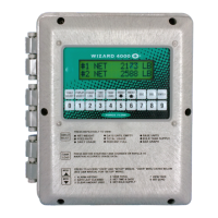
MOUNT INDICATOR
- Connect dedicated clean 110 volt AC power line through 1/2" conduit connector.
- Connect load cell cables through 1/4" cord connector.
- Connect 4-20mA signals through 1/2" conduit connector.
- Connect communications through 1/2" conduit connector.
- Connect relays through 1/2" conduit connector.
- Adjust "Display Adjust" if necessary
WIRE INDICATOR - TURN OFF ALL POWER BEFORE WIRING !
- Check all default settings in "Set-Up Codes" and if necessary,
make changes to better fit your application.
NOTE: Any changes to Set-Up Code "9080 SCALE SET-UP"
will require recalibration of your scale.
CUSTOM FORMATTING
- Tighten all six (6) door screws to maintain NEMA 4X seal in box.
- Double check all cord connectors for tight seal.
- Double check all 1/2" conduit connectors for tight seal.
SEAL INDICATOR ENVLOSURE TO MAINTAIN 4X RATING !!!
(Section W.1.101: "Instllation of Scale Platform & Load Cell)
(Section W.1.201 thru W.1.204: Installation and Wiring of Indicator)
(Section W.1.201: Installation and Wiring of Indicator)
(Section W.1.201: Installation and Wiring of Indicator)
(Section W.2.201 thru W.3.301: Custom Formatting Your Scale