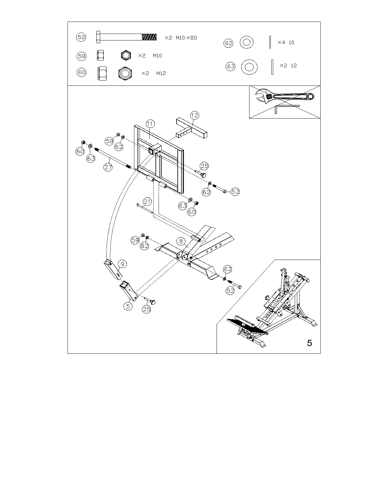
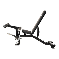
1. Attach the Adjuster (9) to the Foot Stand (11) with M10x80 Bolt (52), Washers (62) and
M10 Nut (59)
2. Attach the Adjuster (5) to the Skew Frame (8) with M10x80 Bolt (52), Washers (62) and
M10 Nut (59)
3. Slide the M12x270 Stud Bolt (27) through the Foot Stand (11) and Skew Frame (8), then
secure with Washers (63) and M12 Nuts (60)
4. Slot the lower part of the Adjuster (9) into the Adjuster (5) and position a Magnetic Pin
(25)