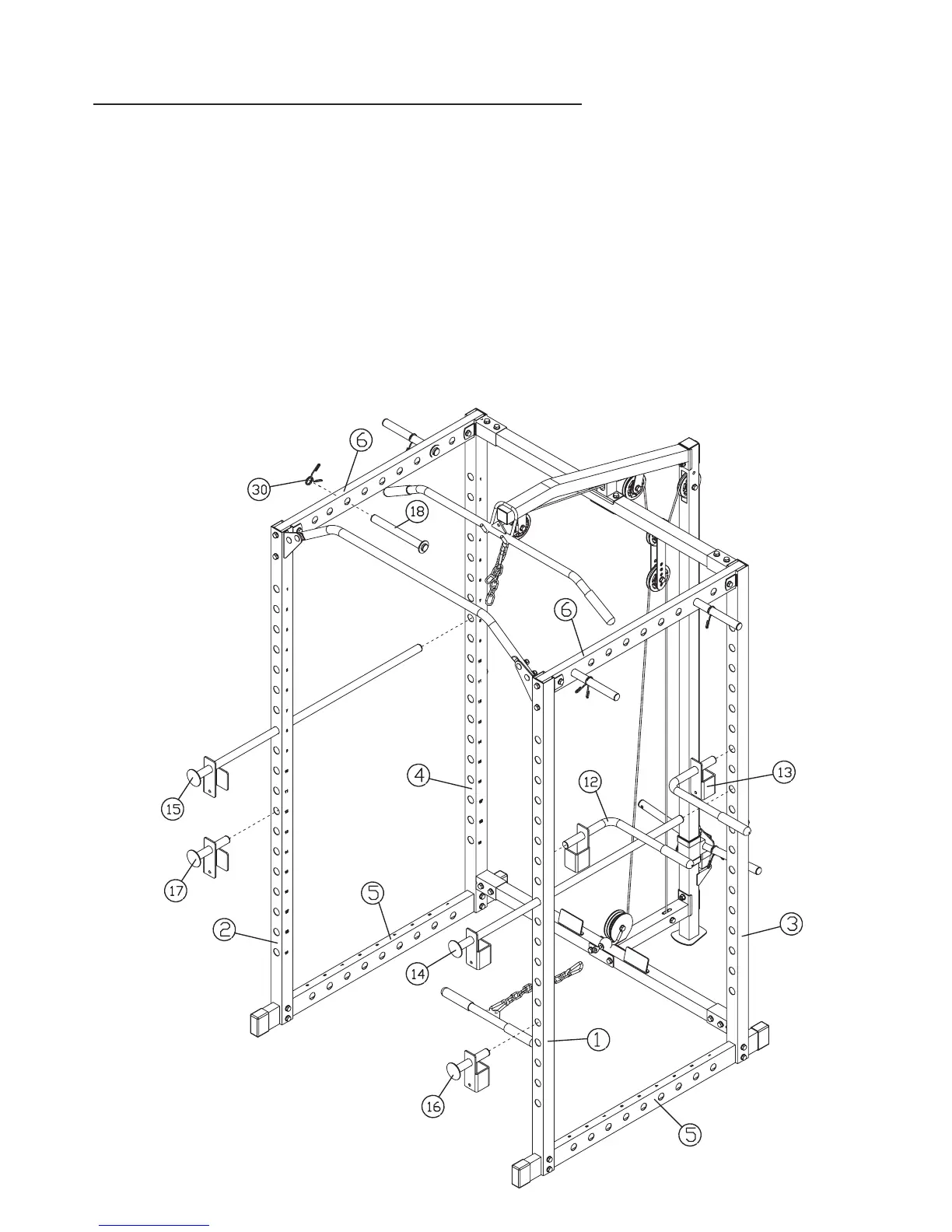
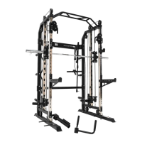
Insert two LONG WEIGHT POSTS (18) into each UPPER SIDE FRAME (6). Space
11
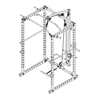
ASSEMBLY DIAGRAM 7
REMEMBER: Only hand tighten all nuts and bolts until whole F-HPR is assembled
1. Attach an END CAP (32) to the open end of the LEFT BAR HOLDER (14) and the RIGHT BAR HOLDER (15)
2. Insert the LEFT BAR HOLDER (14) and the RIGHT BAR HOLDER (15) into the weight holes about half way up the front of
the front VERTICAL BEAMS (1+2) and through to the holes on the REAR VERTICAL FRAMES (4+5)
3. Attach an END CAP (32) to the open end of the LEFT SAFETY CATCH (16) and the RIGHT SAFETY CATCH (17)
4. Insert the LEFT SAFETY CATCH (16) and the RIGHT SAFETY CATCH (17) into the weight holes on the front of the
VERTICAL BEAMS (1+2), below the level of the BAR HOLDERS (14+15)
5. Attach an END CAP (32) to each end of all the LONG WEIGHT POSTS (18)
6. them
equally apart. Clip a SPRING CLIP (30) onto the end of each weigh post.
7. Assemble the ARM SUPPORTS (12+13) by attaching an END CAP (32) to the short end, and sliding a GRIP (38) onto the
long end. (
Skip this step if already pre-assembled)
8. Insert the ARM SUPPORTS (12+13) into the inner holes on the LEFT VERTICAL BEAM (1) and the REAR LEFT VERTICAL
FRAME (3), above the level of the LEFT BAR HOLDER (14)