4
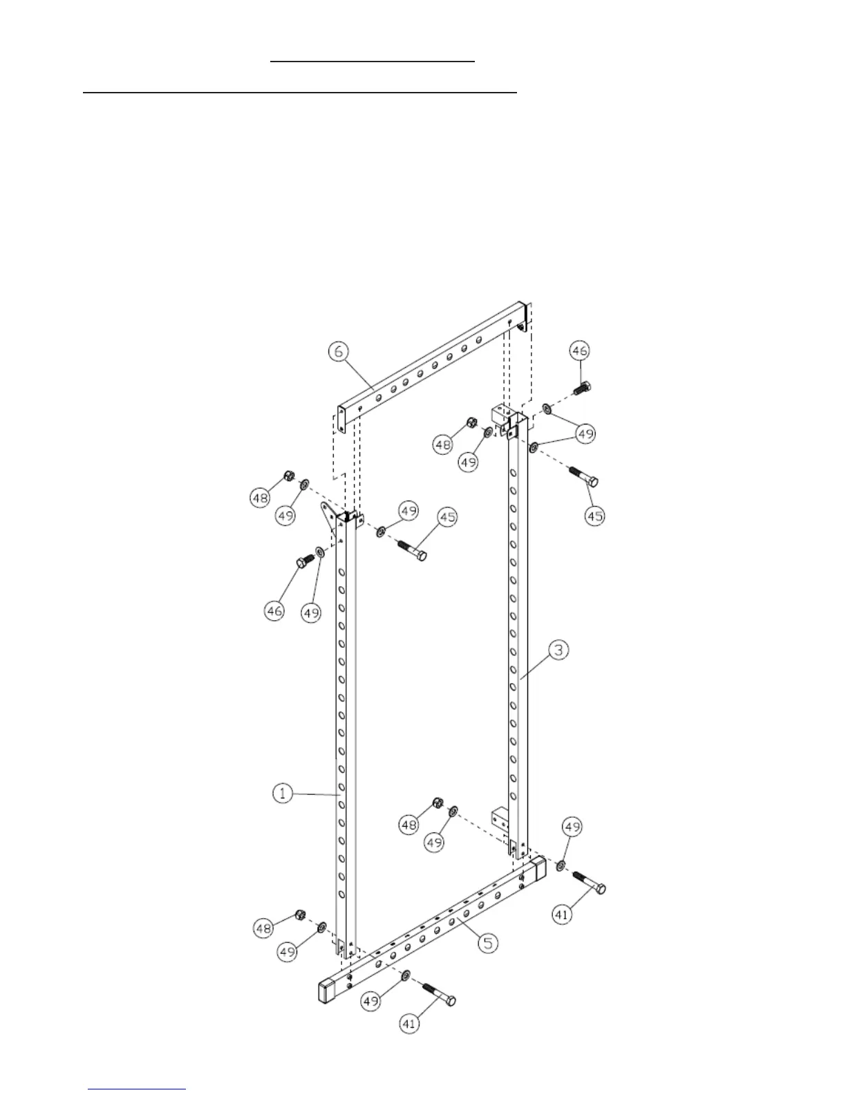
ASSEMBLY DIAGRAM 1 USE A PARTNER TO HELP IN THIS STEP
REMEMBER: Only hand tighten all nuts and bolts until whole F-HPR is assembled
1. Attach the four BASE FRAME END CAPS (37) to the ends of both MAIN BASE FRAMES (5) (
Skip this step if already pre-
assembled)
2. Attach the LEFT VERTICAL BEAM (1) to the MAIN BASE FRAME (5) using two HEX BOLT M10X65 (41), four WASHER10
(49) and two AIRCRAFT NUT M10 (48)
3. Attach the REAR LEFT VERTICAL FRAME (3) to the MAIN BASE FRAME (5) using two HEX BOLT M10X65 (41), four
WASHER10 (49) and two AIRCRAFT NUT M10 (48)
4. Position the UPPER SIDE FRAME (6) between the top of the vertical frames. Attach through the bracket using a HEX
BOLT M10X55 (45), two WASHER10 (49) and an AIRCRAFT NUT M10 (48) on each side. Attach through the outer side
bolt holes at the top of the vertical frames using a HEX BOLT M10X20 (46) and a WASHER10 (49) on each side.