5
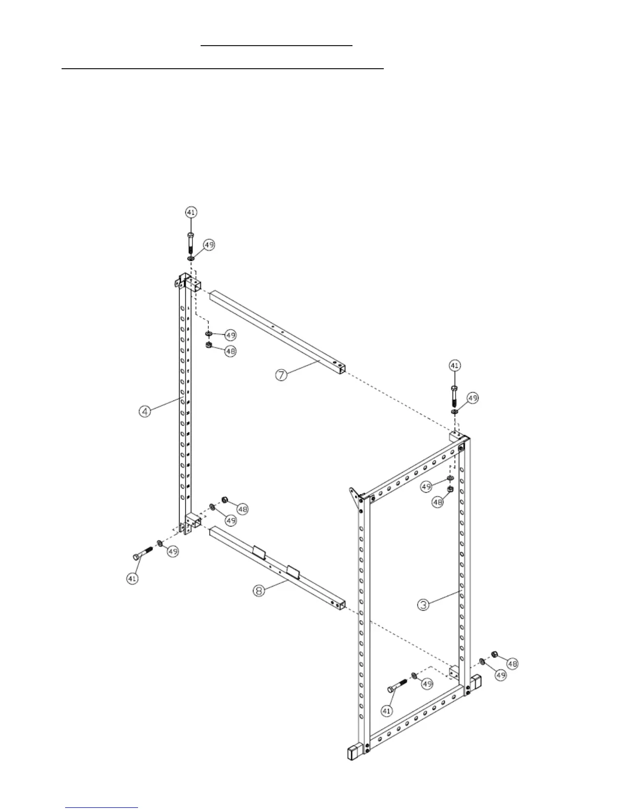
ASSEMBLY DIAGRAM 2 USE A PARTNER TO HELP IN THIS STEP
REMEMBER: Only hand tighten all nuts and bolts until whole F-HPR is assembled
1.
Attach the REAR BASE FRAME (8) to the bottom socket of the REAR LEFT VERTICAL FRAME (3) using two HEX
BOLT M10X65 (41), four WASHER10 (49) and two AIRCRAFT NUT M10 (48)
2. Attach the REAR TOP BEAM (7) to the top socket
of the REAR LEFT VERTICAL FRAME (3) using two HEX BOLT
M10X65 (41), four WASHER10 (49) and two AIRCRAFT NUT M10 (48)
3.
Attach the REAR BASE FRAME (8) to the bottom socket of the REAR RIGHT VERTICAL FRAME (4) using two HEX
BOLT M10X65 (41), four WASHER10 (49) and two AIRCRAFT NUT M10 (48)
4. Attach the REAR TOP BEAM (7) to the top socket
of the REAR RIGHT VERTICAL FRAME (3) using two HEX BOLT
M10X65 (41), four WASHER10 (49) and two AIRCRAFT NUT M10 (48)