9
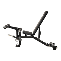
ASSEMBLY DIAGRAM 6
REMEMBER: Only hand tighten all nuts and bolts until whole F-HPR is assembled
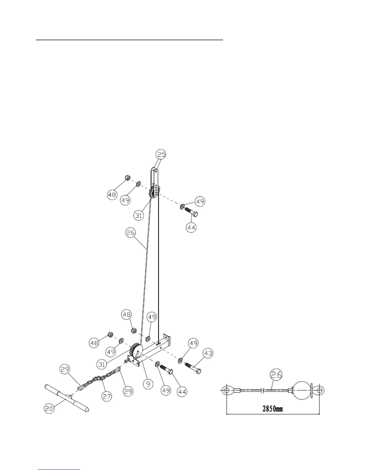
1. Position the stoppered end of a CABLE (26) at the front of the BASE FRAME (9) and draw the cable through the circular
bracket.
2. Position a PULLEY (31) in the circular socket so the cable runs underneath the pulley. Attach using a HEX BOLT M10X45
(44), two WASHER10 (49) and an AIRCRAFT NUT M10 (48)
3. Draw the CABLE (26) upward to the FLOATING PULLEY BRACKET (25), position a PULLEY (31) between the brackets so
the cable will run over the top of the pulley. Attach using a HEX BOLT M10X45 (44), two WASHER10 (49) and an
AIRCRAFT NUT M10 (48)
4. Draw the CABLE (26) down to the slit on the top of the BASE FRAME (9). Attach the end of the cable inside the slit using
a HEX BOLT M10X60 (43), two WASHER10 (49) and an AIRCRAFT NUT M10 (48)
5. Attach a GRIP (38) to each end of the STRAIGHT BAR (20) (
Skip this step if already pre-assembled)
6. Clip the STRAIGHT BAR (20) to a HOOK (29). Connect the hook to the LONG CHAIN (27). Attach a HOOK (29) to the
other end of the chain and clip to the front end of the CABLE (26)