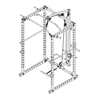
ASSEMBLY DIAGRAM 8
USE A PARTNER TO HELP WITH THIS STEP
REMEMBER: Only hand tighten all nuts and bolts until whole F-ULPHS is assembled.
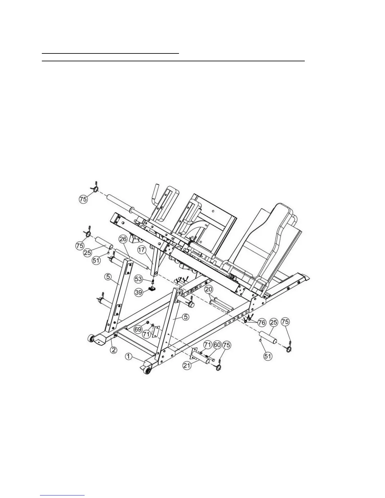
1. Attach the Weights Stow Brackets (Key #21) on both sides of the Support Frame (Key #5) and secure
with 120×70×3 Bracket (Key #32), M10×70 Hex Bolt (Key #60), Washer 10 (Key #71), and M10 Aircraft
Nut (Key #69).
2. Slide the Weights Posts (20) onto the holes found in the Left Stabilizer (Key #1) and Right Stabilizer
(Key #2).
3. Insert the Barbell Rod (Key #26) to the hole in the Lower Weight Carriage (Key #25), then slot the
Barbell Sleeve (Key #25) to the Barbell Rod (Key #26) and lock with M8×8 Allen Screw (Key #51).
4. Place an End Cap (Key #39) over the open end of the Lower Weight Carriage (Key #17) and secure
with M8×25 Allen Bolt (Key #53).