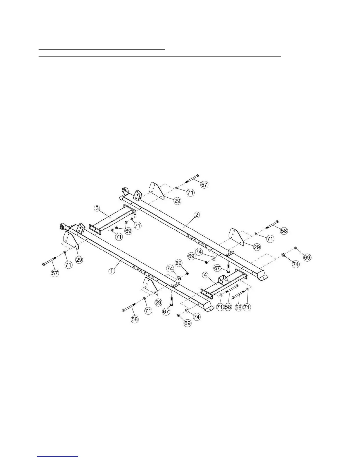
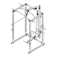
ASSEMBLY DIAGRAM 1
USE A PARTNER TO HELP WITH THIS STEP
REMEMBER: Only hand tighten all nuts and bolts until whole F-ULPHS is assembled.
1. Ensuring correct orientation, attach the Front Connecting Frame (Key #3) to the Left Stabilizer
(Key #1) and Right Stabilizer (Key #2) using 240×158×5 Bracket (Key #29), M10×125 Hex Bolt
(Key #57), Washer 10 (Key #71), and M10 Aircraft Nut (Key #69).
2. Attach the Rear Connecting Frame (Key #4) to the same Left Stabilizer (Key #1) and Right
Stabilizer (Key #2) using M10×120 Hex Bolt, Washer 10 (Key #71), Larger Washer (Key #74),
and M10 Aircraft Nut (Key #69).
3. Attach two 240×158×5 Bracket (Key #29) to the Left Stabilizer (Key #1) and Right Stabilizer (Key
#2) using M10×120 Hex Bolt (Key #58), Washer 10 (Key #71), Larger Washer (Key #74), and
M10 Aircraft Nut (Key #69).
4. Insert M10×70 Carriage Bolts (Key #67) to the Left Stabilizer (Key #1) and Right Stabilizer (Key
#2) [Continue in Diagram 2].