ASSEMBLY DIAGRAM 7
USE A PARTNER TO HELP WITH THIS STEP
REMEMBER: Only hand tighten all nuts and bolts until whole F-ULPHS is assembled.
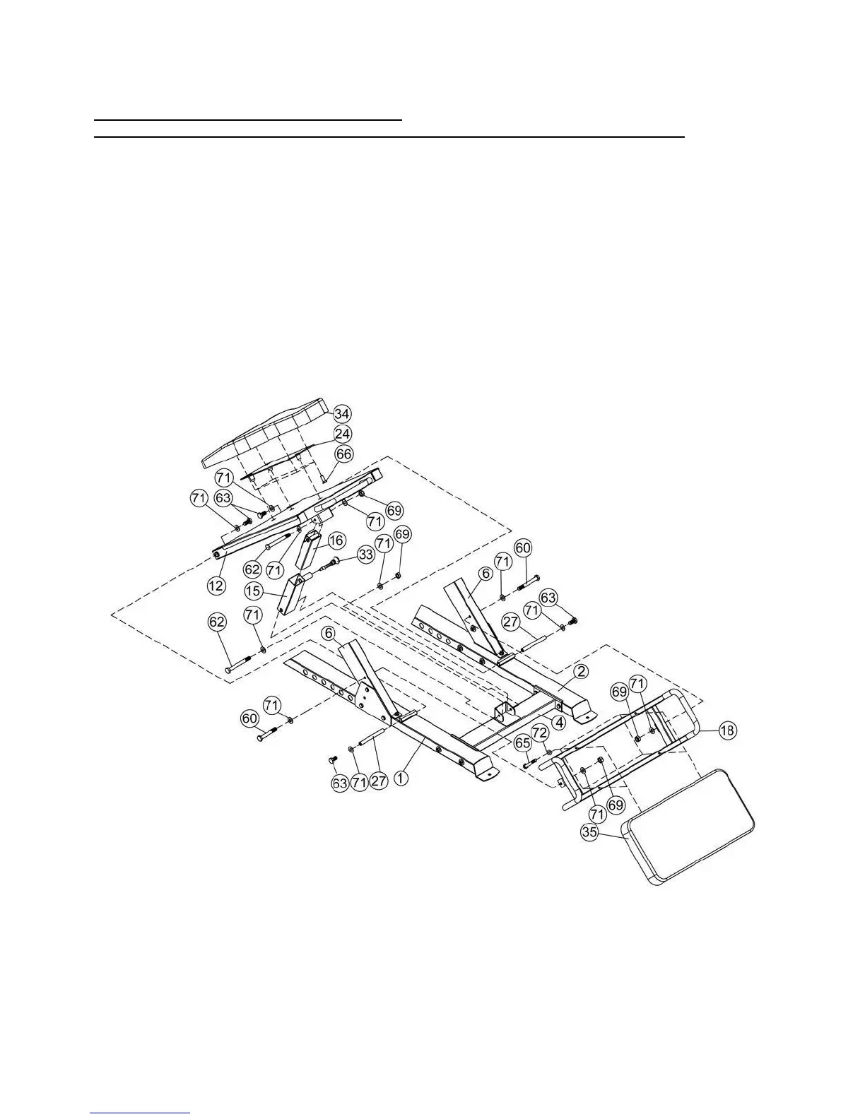
1. Ensuring correct orientation, connect the Lower Adjuster (Key #12) to the Left Stabilizer (Key #1) and
Right Stabilizer (Key #2) using M10×20 Hex Bolt (Key #63), Washer 10 (Key #71), and Axle (Key #27).
2. Connect Adjuster-Outside (Key #15) and Adjuster-Inside (Key #16) together using a Moving Lock Pin
(Key #33).
3. Attach the connected Adjusters (Keys #15 & #16) at the back of the Lower Adjuster (Key #12) and
secure with M10×95 Hex Bolt (Key #62), Washer 10 (Key #71) and M10 Aircraft Nut (Key #69).
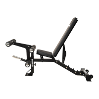
5. Put together the Backrest Pad (Key #34) and the Backrest Pad Mount (Key #24), then attach to the
Lower Adjuster (Key #12) and secure using Socket Countersunk Head Screw (66).
6. Place Seat Pad (Key #3535) onto the Seat Frame (Key #18) and secure with M8×65 Hex Both (Key
#65) and Washer 8 (Key #72), then attach to the Frame (6) using M10×70 Hex Bolt (Key #60), Washer
10 (Key #71), and M10 Aircraft Nut (Key #69).