ASSEMBLY DIAGRAM 6
USE A PARTNER TO HELP WITH THIS STEP
REMEMBER: Only hand tighten all nuts and bolts until whole F-ULPHS is assembled.
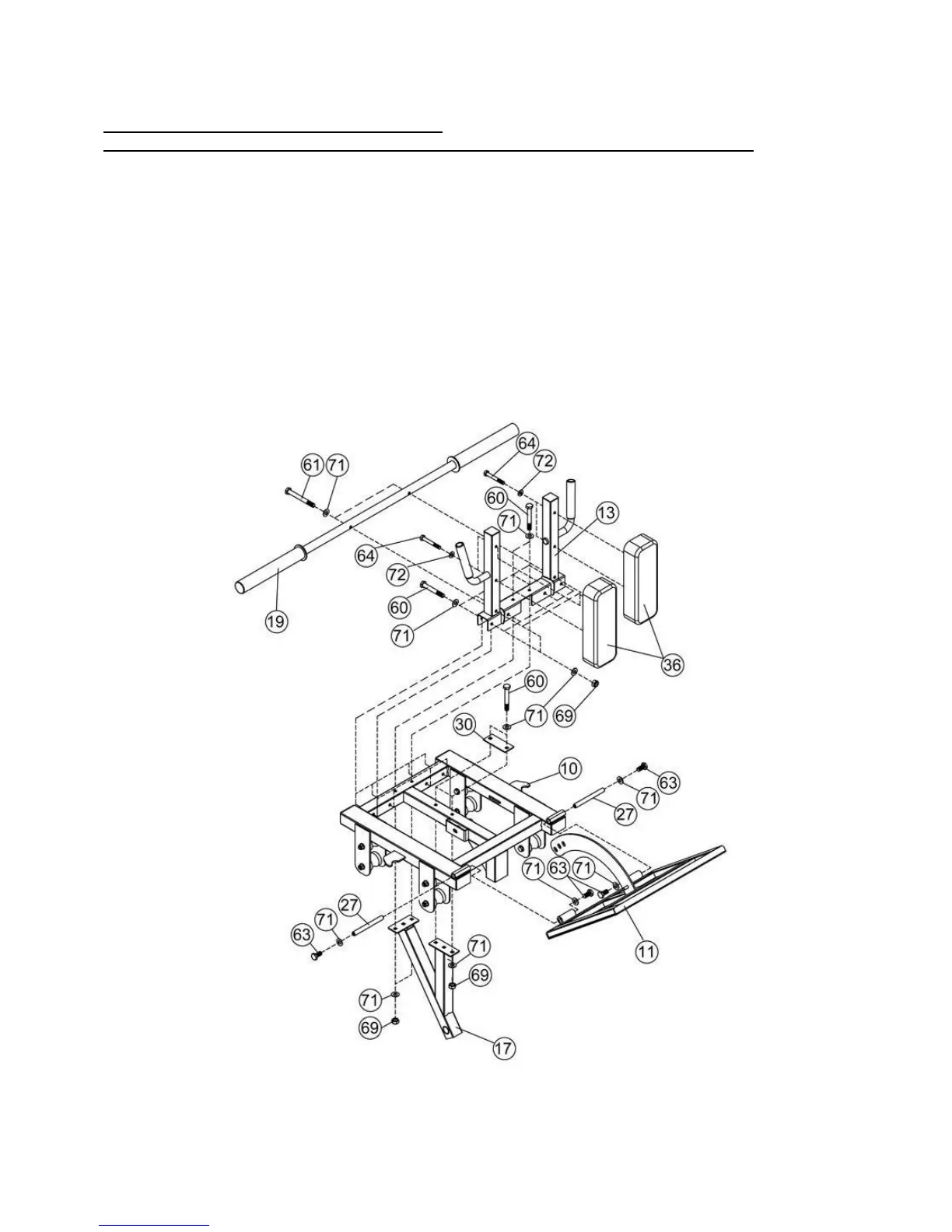
1. Attach the Lower Weight Carriage (Key #17) beneath the Sliding Frame (Key #10) and slot the
Shoulder Pad Mount (Key #13) above the Sliding Frame (Key #10), then connect both using
120×50×3 Bracket (Key #30), M10×70 Hex Bolt (Key #60), Washer 10 (Key #71), and M10
Aircraft Nut (Key #69).
2. Attach two Shoulder Pads (Key #36) to the Shoulder Pad Mount (Key #13) and secure using
M8×60 Hex Bolt (Key #64) and Washer 8 (Key #72).
3. Behind the Shoulder Pad Mount (Key #13), attach the Upper Weight Carriage (Key #19) using
M10×90 Hex Bolt (Key #61), Washer 10 (Key #71), and M10 Aircraft Nut (Key #69).
4. Connect the Upper Adjuster (Key #11) to the Sliding Frame (Key #10) using M10×20 Hex Bolt
(Key #63), Washer 10 (Key #71), and Axle (Key #27).