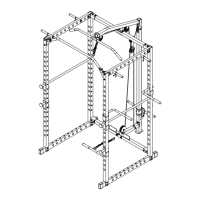
ASSEMBLY DIAGRAM 5
USE A PARTNER TO HELP WITH THIS STEP
REMEMBER: Only hand tighten all nuts and bolts until whole F-ULPHS is assembled.
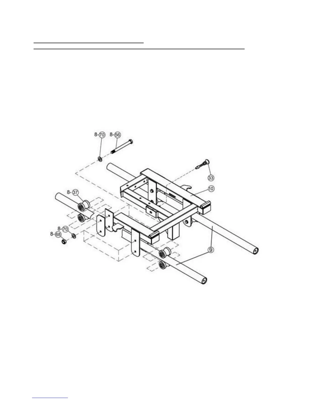
1. Sliding Frame Assembly: Position Rollers (Key #37) on top and below of the Guide Rods (Key
#9) and slide inside the Sliding Frame (Key #10) brackets, then secure with M12×110 Hex Bolt
(Key #56), Washer 12 (Key #70) and Socket Countersunk Head Screw (Key #68).
NOTE: Insert Guiding Rods inside Sliding Frame before securing the rods to the Upper
Crossmember (Key #8) and Lower Crossmember (Key #7) (Diagram 3)