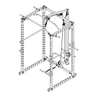
ASSEMBLY DIAGRAM 4
USE A PARTNER TO HELP WITH THIS STEP
REMEMBER: Only hand tighten all nuts and bolts until whole F-ULPHS is assembled.
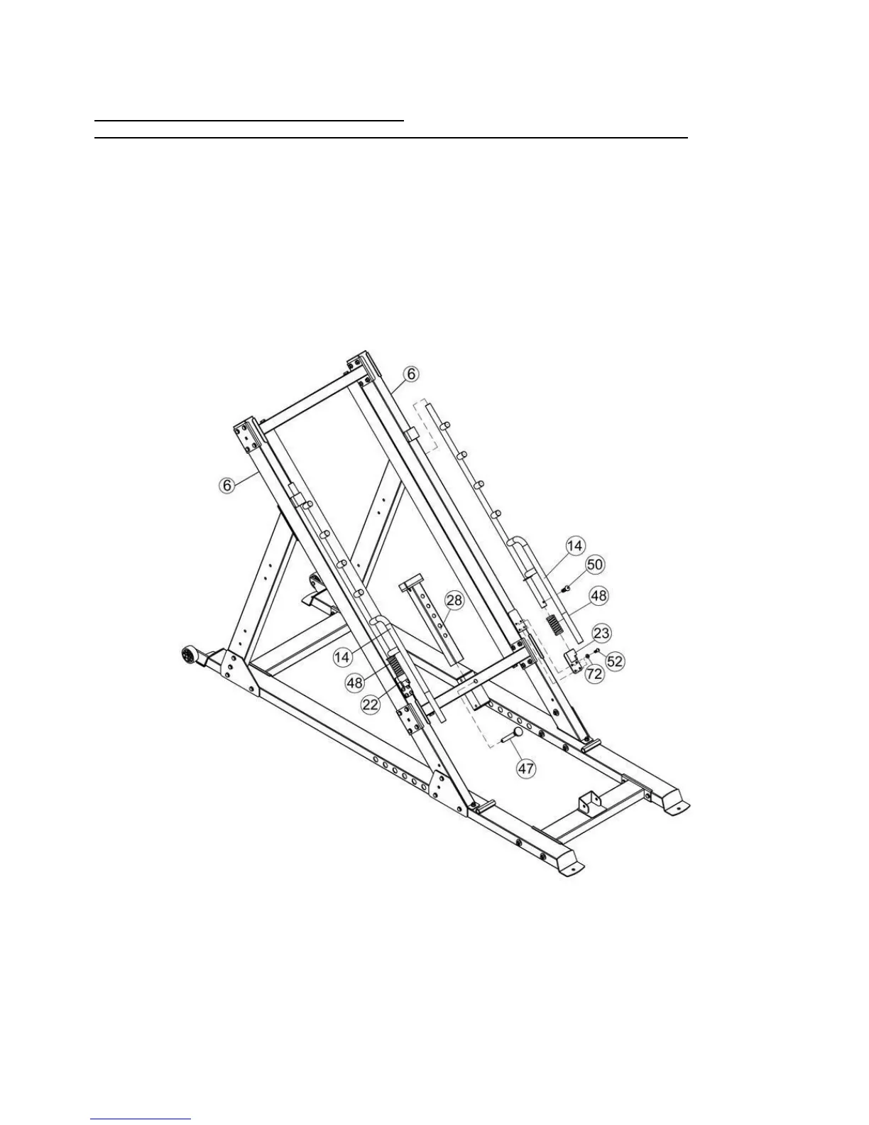
1. Attach Safety Support (Key #28) to the Lower Crossmember (Key #7) and lock with Lock Pin
(Key #47).
2. Insert Spring (Key #48) and Attach Lock Out (Key #14) to both Frames (Key #6) using Hexagon
Socket Button Head Screw (Key #50).
3. Slide the upper end of the Lock Out (Key #14) to the bracket and attach Lock Out Left (Key #22)
and Lock Out Right (Key #23) to both Frames (Key #6) using M8×16 Allen Bolt (Key #52) and
Washer 8 (Key #72).