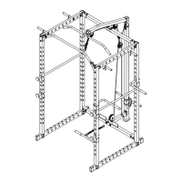
ASSEMBLY DIAGRAM 3
USE A PARTNER TO HELP WITH THIS STEP
REMEMBER: Only hand tighten all nuts and bolts until whole F-ULPHS is assembled.
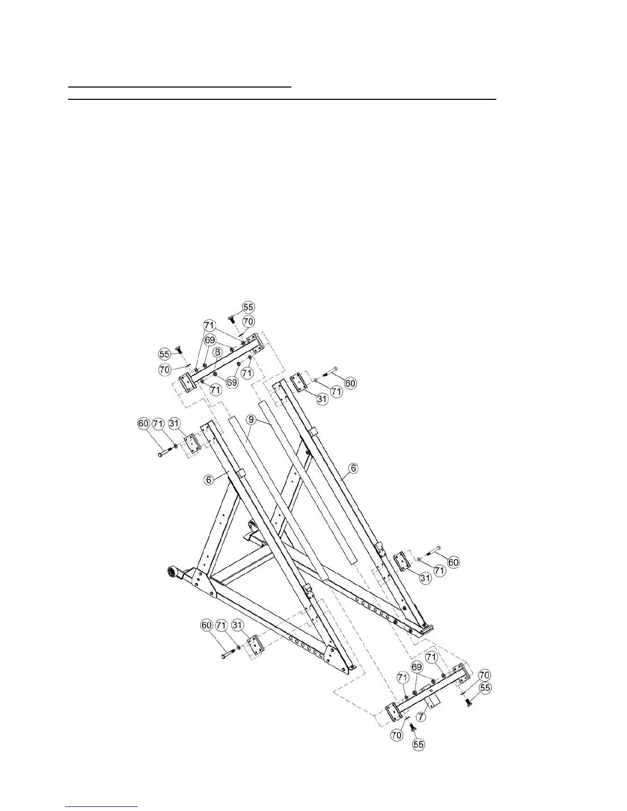
1. Attach the Upper Crossmember (Key #8) into the top of the Frames (Key #6) and connect using
120×101×4 Bracket (Key #31), M10×70 Hex Bolt (Key #60), Washer 10 (Key #71), and M10
Aircraft Nut (Key #69).
2. Attach Lower Crossmember (Key #7) into the lower part of the Frames (Key #6) and connect
using 120×101×4 Bracket (Key #31), M10×70 Hex Bolt (Key #60), Washer 10 (Key #71), and
M10 Aircraft Nut (Key #69).
3. Place two Guide Rods (Key #9) between the Frames (Key #6) and attach to the Upper
Crossmember (Key #8) and Lower Crossmember (Key #7) using M12×25 Hex Bolt (Key #55)
and Washer 12 (Key #70).
Note: Secure Guide Rods (Key #9) after Diagram 6 is assembled.