Next Generation Firewall Hardware Guide | Models N120W, N120WL,and N120L
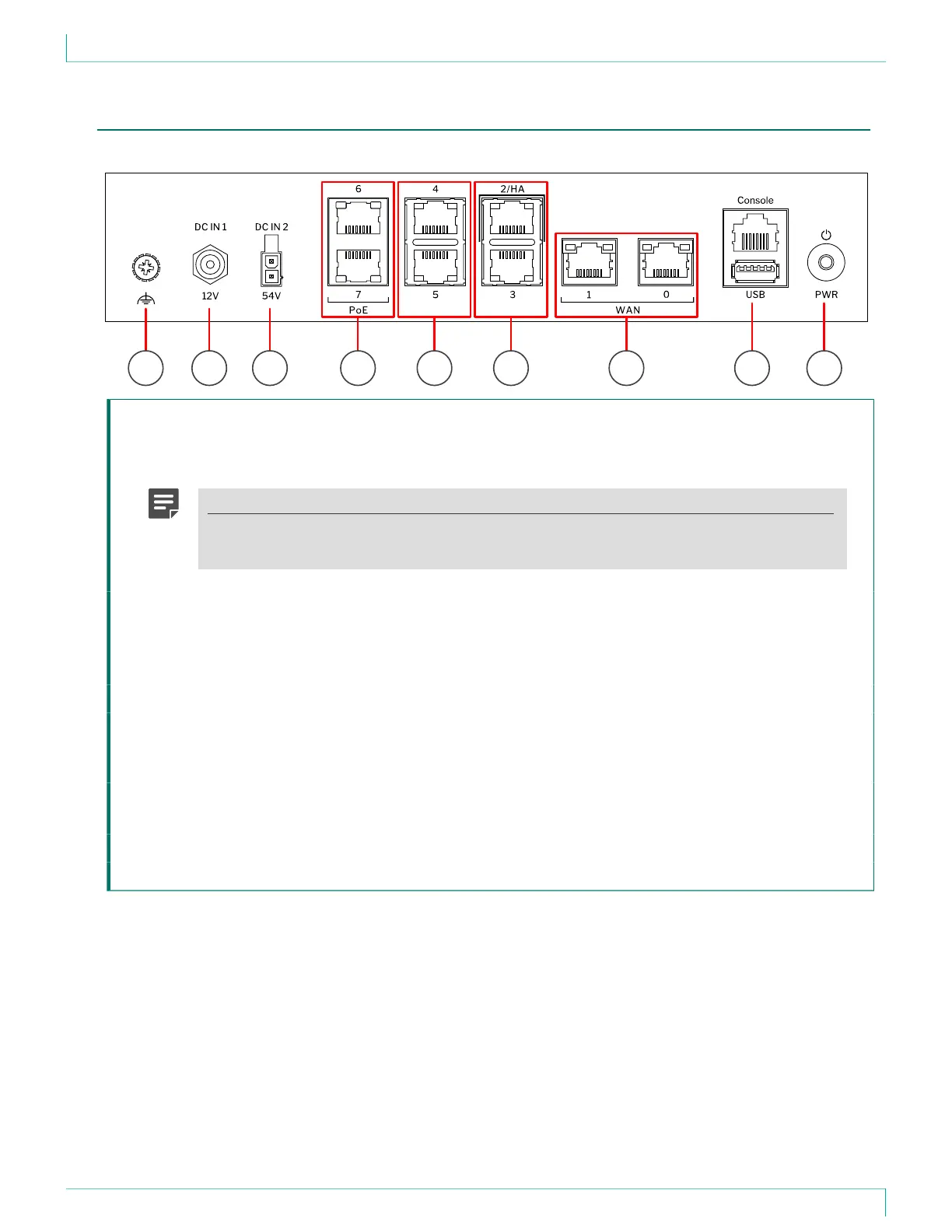
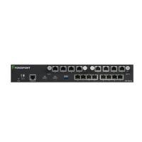
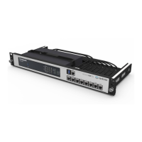
Back panel
This panel has the following parts.
71 2 3 8 94 5 6
1 Grounding point
2 Power connector DC IN 1 — Provides 12V DC power for the appliance.
3 Power connector DC IN 2 — Optionally provides 54V DC power for the power over Ethernet (PoE) ports.
Note
PoE is an optional feature. A power adapter and power cable for PoE are not included with
the delivery. To use PoE, you must purchase them separately.
4 Fixed Ethernet ports 6 and 7 from top to bottom.
When a power adapter is connected to power connector DC IN 2, fixed Ethernet ports 6 and 7 provide
power over the Ethernet cable for other devices that are compatible with the 802.3at standard.
PoE on these ports is active and uses LLDP for power negotiation.
5 Fixed Ethernet ports 4 and 5 from top to bottom.
6 Fixed Ethernet ports 2 and 3 from top to bottom.
If you use the appliance in an NGFW Engine cluster, use fixed Ethernet port 2 for the heartbeat
connection between the nodes.
7 Fixed Ethernet ports 1 and 0 from left to right.
Ethernet ports 1 and 0 are intended for the WAN connection.
8 Console port (speed 115,200 bps) and USB port
9 Power button.
4