Do you have a question about the Forcepoint V5000 G2 and is the answer not in the manual?
Check included items like Ethernet, Power, Serial cables, and bezel for completeness.
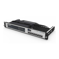
Secure the appliance to a rack tray using mounting screws on the front.
Choose between Web Security or Email Security mode based on subscription.
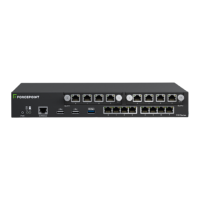
Connect required ports (C, P1, N) based on Web or Email security mode.
Connect a computer or terminal server via null modem or straight-through cable.
Connect a monitor and keyboard directly or via KVM switch.
Verify power button and rear LEDs (NICs, system status) are illuminated.
Configure security mode, management interface, NTP, and network interfaces.
Configure Forcepoint Security Manager and Content Gateway Manager.
Configure Forcepoint Security Manager and email DLP policies.
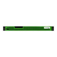
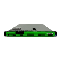
The Forcepoint V5000 G2/G3 is a security appliance designed to provide either web or email security, depending on the chosen configuration. It supports two primary security modes: Web (Forcepoint Web Security or Forcepoint URL Filtering) and Email (Forcepoint Email Security). The appliance's function is to act as a central point for managing and enforcing security policies for network traffic.
In Web mode, the appliance acts as a Content Gateway proxy, receiving and processing Internet requests. It works in conjunction with Forcepoint Security Manager to enforce web security policies, filter URLs, and manage user access to web content. The appliance handles database downloads from the Internet to keep its security definitions up-to-date.
In Email mode, the appliance is designed to receive and send mail, providing Forcepoint Email Security. It manages personal email and cluster communication, and requires access to a mail server for full functionality. Similar to web mode, it integrates with Forcepoint Security Manager to enforce email security policies, including Data Loss Prevention (DLP) policies.
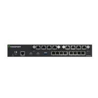
The appliance uses various network interfaces to perform its functions:
The V5000 G2/G3 appliance is designed for integration into a network infrastructure, often alongside a separate computer running Windows Server for the Forcepoint Security Manager.
The appliance supports various deployment scenarios, from a single appliance to multiple appliances on a network. The deployment diagram illustrates a basic setup where the appliance interacts with a router, firewall, and clients, all managed by the Forcepoint Security Manager.
The manual primarily focuses on initial setup and configuration rather than ongoing maintenance. However, some aspects imply maintenance considerations:
| Model | Forcepoint V5000 G2 |
|---|---|
| Category | Firewall |
| VPN Support | Yes |
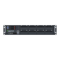
| Form Factor | 1U Rackmount |
| Power Supply | Dual, Hot Swappable |
| Network Interfaces | 8x 1GbE, 4x 10GbE SFP+ |