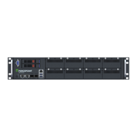
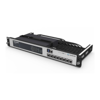
2. Place appliance on tray
and secure to server rack
using mounting screws on
front of appliance.
2
Rack Installation
To mount the V5000 appliance, use a rack tray or rail kit (not
included). If using a rack tray:
1. Install rack tray into desired server rack.
©2019 Forcepoint. All rights reserved.
Quick Start Guide
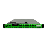
Forcepoint V5000 G4R2
Web or Email Security Appliance
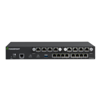
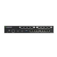
Connect the appliance interfaces required by the security mode for this appliance. Cat 5E cables (or
better) are required. Do not use crossover network cables.
Rack tray/rail kit not included. Optional Static Rail Kit available.
Contact your Forcepoint account representative.
Contact Forcepoint Technical Support if any items are missing.
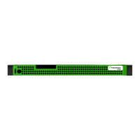
Bezel (faceplate)
Ethernet Cables (4)
Power Cable
Serial Cable
G4R2
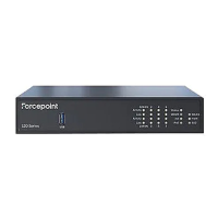
Power on the appliance and check the following indicators:
Contact Forcepoint Technical Support if any indicators are not
illuminated correctly.
6
Power On Appliance
Front
• Power button is illuminated.
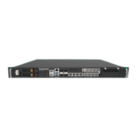
Rear
• LEDs for connected interfaces (NICs) are green.
• System status indicator (LED left of power supplies) is solid
blue.
Please refer to the Forcepoint Appliances Getting Started guide
for more details.
Initial Configuration
Firstboot Script
• Configure security mode.
• Configure the appliance management communication
interface (C).
• Configure NTP servers/system time.
Appliance Command Line
• Configure applicable network interfaces.
• Configure other settings as desired.
Web Mode
Forcepoint Security Manager
• Enter subscription key, update Master Database, configure
Network Agent, and configure policies in Forcepoint
Security Manager.
• Requires Windows Server (see latest Security Manager
release notes for supported versions).
Content Gateway Manager (proxy)
• If your site uses the Forcepoint proxy, configure user
authentication and select protocols.
Email Mode
Forcepoint Security Manager
• Complete configuration wizard, enter subscription key, and
configure policies in the Email Security module. Configure
email DLP policies in the Data Security module.
• Requires Windows Server (see latest Security Manager
release notes for supported versions).
QSG240-100_RevA
*Not used for Forcepoint URL Filtering.
iDRAC
P1
C N
P2
Connect to the appliance via serial port or KVM in order to access the command line interface for initial
configuration. Serial port settings are: 9600 baud, 8 bits, no parity.
Notes:
• Get the default iDRAC password from the Dell information tag.
• Best practice: Secure power cables using velcro straps and plug power cables into an
appropriate power source.
Serial Port
iDRAC
KVM
7
4
1
5
Connect Input Device & Power On
Configuration Overview
Connect Network Cables
Verify Contents
Plan your deployment before setting up the appliance. See the
back of this guide for a deployment overview and reference sheet.
Before you begin...
The appliance supports the following security modes:
3
Determine Security Mode
Based on your subscription and deployment plan, determine the appropriate security mode for this
appliance.
• Web (Forcepoint Web Security or Forcepoint URL Filtering)
• Email (Forcepoint Email Security)