Note: With modern ignition systems the only
suitable way to time the ignition accurately is
with a stroboscopic timing light. However, for
initial setting up purposes (ie after major
overhaul, or if the timing has been otherwise
completely lost) a basic initial static setting
may be used to get the engine started Once
the engine is running, the timing should be
accurately set using the timing light. Before
carrying out any of the following, ensure that
the contact breaker points are correctly
adjusted as described in Section 13.
1 In order that the engine can run efficiently, it
is necessary for a spark to occur at the spark
plug and ignite the fuel/air mixture at the
instant just before the piston on the
compression stroke reaches the top of its
travel. The precise instant at which the spark
occurs is determined by the ignition timing
and this is quoted in degrees before top dead
centre (BTDC).
2 If the timing is being checked as a
maintenance or service procedure, refer to
paragraph 11 onwards. If the distributor has
been dismantled or renewed, or if its position
on the engine has been altered, obtain an
initial static setting as follows.
Static setting
3 Pull off the plug lead and remove No 1
spark plug (nearest the crankshaft pulley).
4 Place a finger over the plug hole and turn
the crankshaft in the normal direction of
rotation (clockwise from the crankshaft pulley
end) until pressure is felt in No 1 cylinder. This
indicates that the piston is commencing its
compression stroke. The crankshaft can be
turned with a spanner on the pulley bolt.
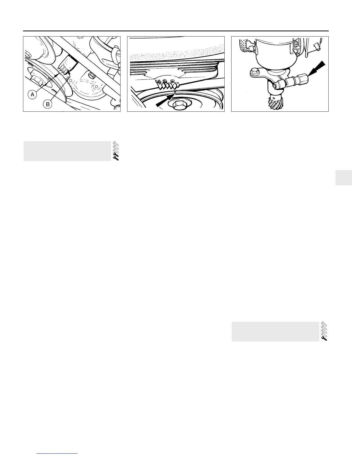
5 Continue turning the crankshaft until the
notch on the pulley is aligned with the
appropriate mark on the timing scale for the
engine being worked on (see Specifications).
On OHV engines the timing scale is cast into
the timing cover and situated just above and
to the right of the pulley. On CVH engines the
scale is moulded into the timing belt cover
and is situated directly above the pulley. On
all engines the “O” mark on the scale
represents Top Dead Centre (TDC) and the
raised projections to the left of TDC are in
increments of 4° BTDC (see illustrations).
6 Remove the distributor cap and check that
the rotor arm is pointing towards the No 1
spark plug lead segment in the cap.
7 Slacken the distributor clamp pinch bolt
(OHV engines) or the three distributor flange
securing bolts (CVH engines) (see
illustration).
8 Turn the distributor body anti-clockwise
slightly until the contact breaker points are
closed, then slowly turn the distributor body
clockwise until the points just open. Hold the
distributor body in this position and tighten
the clamp pinch bolt or flange securing bolts
as applicable.
9 Refit the distributor cap, No 1 spark plug
and the plug lead.
10 It should now be possible to start and run
the engine enabling the timing to be
accurately checked with a timing light as
follows.
Stroboscopic setting
11 Refer to the Specifications for the timing
setting applicable to the engine being worked
on and then highlight the appropriate mark on
the timing scale and the notch in the pulley
with a dab of white paint (see paragraph 5).
12 Connect a timing light to the engine in
accordance with the manufacturer’s
instructions (usually between No 1 spark plug
and plug lead).
13 Disconnect the vacuum hose at the
distributor vacuum unit and plug the hose.
14 Start the engine and allow it to idle.
15 Point the timing light at the timing marks.
They should appear to be stationary with the
crankshaft pulley notch in alignment with the
appropriate notch on the scale.
16 If adjustment is necessary (ie the marks are
not aligned) slacken the distributor clamp pinch
bolt or flange securing bolts as applicable, and
turn the distributor body as necessary to align
the marks. Tighten the pinch bolt or flange
bolts when the setting is correct.
17 A secondary use of the timing light is to
check that the centrifugal and vacuum
advance functions of the distributor are
working.
18 The tests are not of course precise as
would be the case if sophisticated equipment
were used, but will at least indicate the
serviceability of the unit.
19 With the engine idling, timing light
connected and vacuum pipe disconnected
and plugged as described in the preceding
paragraphs, increase the engine speed to
2000 rpm and note the approximate distance
which the pulley mark moves out of alignment
with the mark on the scale.
20 Reconnect the vacuum pipe to the
distributor and repeat the test when for the
same increase in engine speed, the alignment
differential of the timing marks should be
greater than previously observed.
21 If the timing marks did not appear to move
during the first test, a fault in the distributor
centrifugal advance mechanism is indicated.
No increased movement of the marks during
the second test indicates a punctured
diaphragm in the vacuum unit, or a leak in the
vacuum line.
22 On completion of the adjustments and
checks, switch off the engine and disconnect
the timing light.
1 The correct functioning of the spark plugs is
vital for the correct running and efficiency of
the engine. It is essential that the plugs fitted
are appropriate for the engine, and the
suitable type is specified at the end of this
chapter. If this type is used and the engine is
in good condition, the spark plugs should not
need attention between scheduled
replacement intervals. Spark plug cleaning is
rarely necessary and should not be attempted
unless specialised equipment is available as
damage can easily be caused to the firing
ends.
15 Spark plug renewal -
RS Turbo models
14 Ignition timing check - models
with contact breaker distributor
Every 6000 miles or 6 Months 1•13
1
14.5b Crankshaft pulley notch (arrowed)
and timing scale - CVH engine
14.7 Distributor clamp pinch-bolt location
(arrowed) - OHV engines
14.5a Timing mark identification -
OHV engines
A Notch on crankshaft pulley
B Timing scale cast into timing cover
 Loading...