Yes
REPLACE the BPP switch; REFER to Section 417-01. CLEAR the DTCs. TEST the system for normal operation.
No
REPAIR circuit 511 (LG). If the concern is not found with the circuit, then REPLACE the GEM; REFER to Section
419-10. CLEAR the DTCs. TEST the system for normal operation.
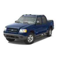
C15 MONITOR THE TR SENSOR PID NTRL_SW
Monitor the PID NTRL_SW.
Verify the PID NTRL_SW indicates NTRL.
Verify the PID NTRL_SW indicates notNTRL when the transmission is in any position other than NEUTRAL.
Does the PID NTRL_SW indicate correctly?
Yes
GO to C19.
No
GO to C16.
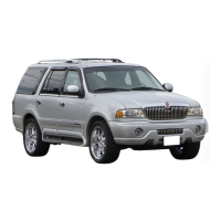
C16 CHECK THE GROUND TO THE DIGITAL TRANSMISSION RANGE (DTR) SENSOR — CIRCUIT 57 (BK)
DTR Sensor C182
Measure the resistance between DTR sensor C182-7, circuit 57 (BK), and ground.
Is the resistance less than 5 ohms?
Yes
GO to C17.
No
REPAIR circuit 57 (BK). CLEAR the DTCs. TEST the system for normal operation.
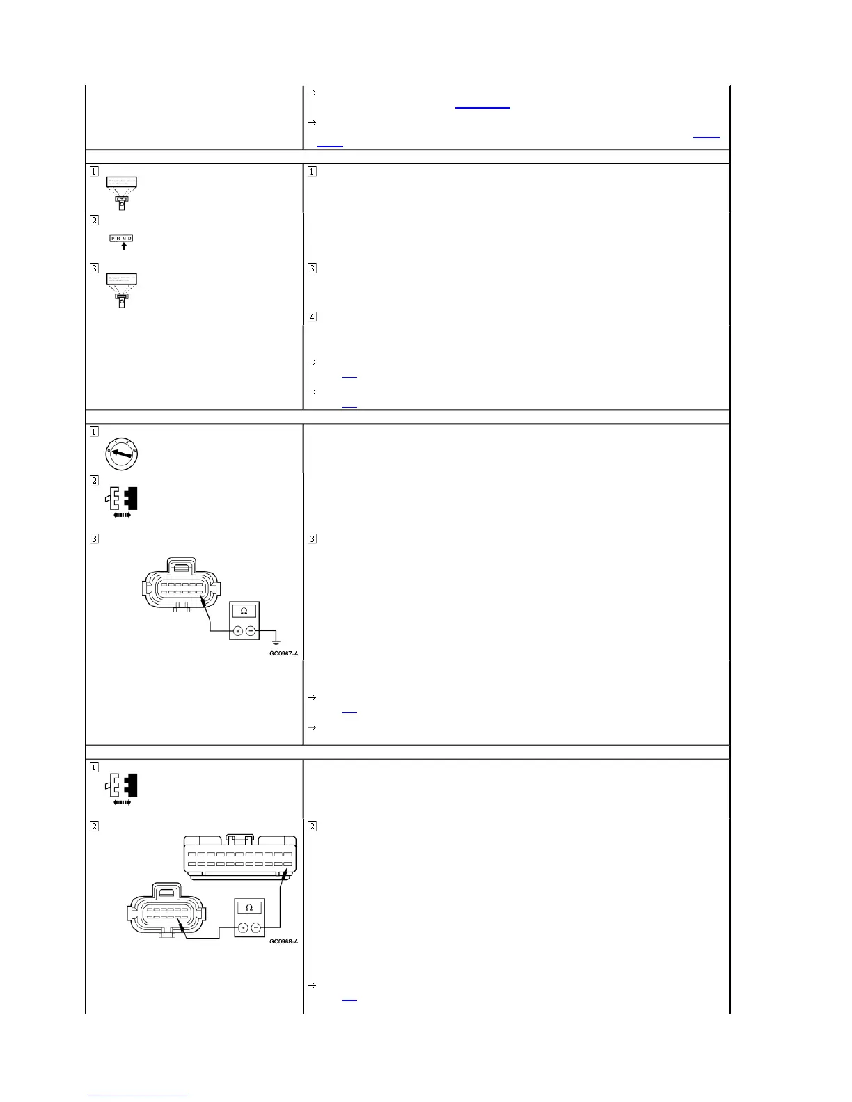
C17 CHECK CIRCUIT 463 (R/W) FOR OPEN
GEM C241
Measure the resistance between DTR sensor C182-8, circuit 463 (R/W), and GEM C241-22, circuit 463 (R/W).
Is the resistance less than 5 ohms?
Yes
GO to C18.
1998 Expedition/Navigator Workshop Manual
http://www.fordtechservice.dealerconnection.com/pubs/content/~WSWJ/~MUS~LEN/21/
 Loading...