Monitor the PID HALLPWR.
Does the PID HALLPWR indicate OFF?
Yes
GO to A9.
No
GO to A8.
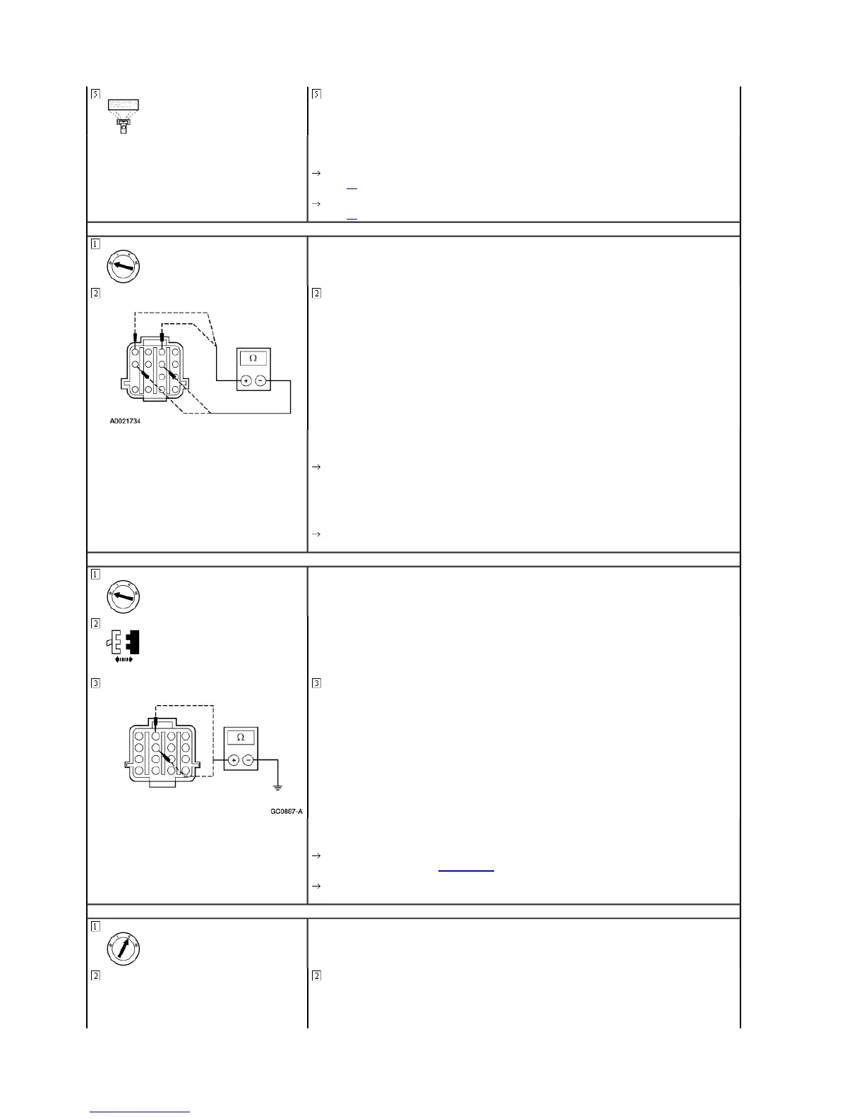
A8 CHECK FRONT AND REAR HALL EFFECT SENSORS
Measure the resistance between transfer case assembly C201 pin 2, circuit 772 (LB) component side and
transfer case assembly C201 pin 6, circuit 682 (DB) component side; and between transfer case assembly C201
pin 4, circuit 435 (Y/LB) component side and transfer case assembly C201 pin 8, circuit 682 (DB) component
side.
Are the resistances less than 10,000 ohms?
Yes
If terminals 2 and 6 are less than 10,000 ohms, REPLACE rear Hall effect sensor. CLEAR the DTCs. TEST the
system for normal operation.
If terminals 4 and 8 are less than 10,000 ohms, REPLACE front Hall effect sensor. CLEAR the DTCs. TEST the
system for normal operation.
No
REPAIR circuit 774 (LG). CLEAR the DTCs. TEST the system for normal operation.
A9 CHECK CIRCUIT 774 (LG) FOR SHORT TO GROUND
GEM C241
Measure the resistance between transfer case assembly C201-3, circuit 774 (LG), and ground; and between
transfer case assembly C201-7, circuit 774 (LG), and ground.
Are the resistances greater than 10,000 ohms?
Yes
REPLACE the GEM; REFER to Section 419-10. CLEAR the DTCs. TEST the system for normal operation.
No
REPAIR circuit 774 (LG). CLEAR the DTCs. TEST the system for normal operation.
A10 MONITOR THE FRONT AND REAR HALL EFFECT PIDS TRA_RSP AND TRA_FSP
Place the mode switch in the A4WD position.
1998 Expedition/Navigator Workshop Manual
http://www.fordtechservice.dealerconnection.com/pubs/content/~WSWJ/~MUS~LEN/21/

 Loading...