Normal Operation
Under normal operation the instrument cluster module grounds the accessory delay relay through circuit 1004 (LB/RD). Power is sent to the driver window control switch through circuit 400
(LB/BK) from the accessory delay relay. The driver window control switch is grounded through circuit 1205 (BK).
Possible Causes
Fuses.
Open in circuits 400 (LB/BK), 1205 (BK) or 1004 (LB/RD).
Damaged accessory delay relay.
Damaged CJB.
Inoperative ICM.
Inoperative driver window control switch.
PINPOINT TEST H: ALL POWER WINDOWS ARE INOPERATIVE
Test Step Result / Action to Take
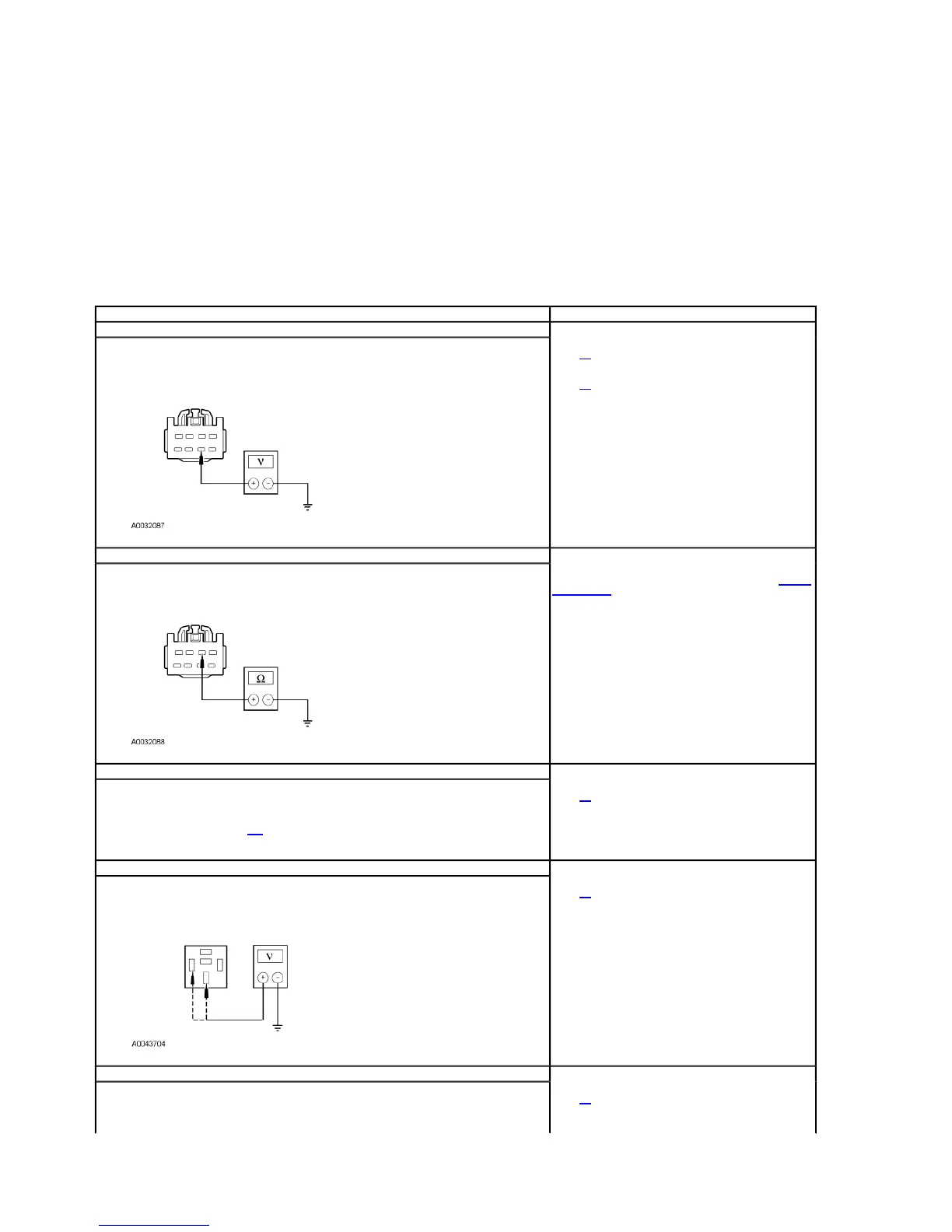
H1 CHECK THE VOLTAGE TO THE DRIVER WINDOW CONTROL SWITCH — CIRCUIT 400 (LB/BK)
Disconnect: Driver Window Control Switch C504a.
Ignition ON.
Measure the voltage between driver window control switch C504a-
6, circuit 400 (LB/BK) harness side and
ground.
Is the voltage greater than 10 volts?
Yes
GO to H2.
No
GO to H3.
H2 CHECK THE GROUND TO THE DRIVER WINDOW CONTROL SWITCH—CIRCUIT 1205 (BK)
Ignition OFF.
Measure the resistance between driver window control switch C504a-2, circuit 1205 (BK) harness side
and ground.
Is the resistance less than 5 ohms?
Yes
INSTALL a new driver window control switch. REFER to Window
Control Switch
in this section. TEST system for normal operation.
No
REPAIR the circuit. TEST the system for normal operation.
H3 CHECK THE ACCESSORY DELAY RELAY
Ignition OFF.
Disconnect: Accessory Delay Relay.
Carry out the accessory delay relay component test.
Refer to Wiring Diagrams Cell 149 for component testing.
Is the accessory delay relay OK?
Yes
GO to H4.
No
INSTALL a new accessory delay relay. TEST the system for
normal operation.
H4 CHECK THE POWER TO THE ACCESSORY DELAY RELAY
Ignition ON.
Measure the voltage between ground and accessory delay relay socket pin 85 and pin 30 harness side.
Is the voltage greater than 10 volts?
Yes
GO to H5.
No
REPAIR the power supply circuit or central junction box (CJB).
TEST the system for normal operation.
H5 CHECK CIRCUIT 400 (LB/BK) FOR AN OPEN
Ignition OFF.
Measure the resistance between driver window control switch C504a-6, circuit 400 (LB/BK) and
accessory delay relay socket pin 87, circuit 400 (LB/BK) harness side.
Yes
GO to H6.
No
2003 Explorer/Mountaineer Workshop Manual
http://www.fordtechservice.dealerconnection.com/pubs/content/~WS3N/~MUS~LEN/19/S