1 1-02-02
Wheels
1 1-02-02
F1416-A
FIG. 2-Front
Hub
and Rotor Bearing and Grease Retainer Disc
Brakes-Typical
2
IN-VEHICLE ADJUSTMENTS AND REPAIRS
HOISTING INSTRUCTIONS
Damage to steering linkage compo-
nents and front suspension struts may
occur if care is not exercised when
positioning the hoist adapters of 2
post hoists prior to lifting the vehicle.
If a 2 post hoist is used to lift the
vehicle, place the adapters under the
lower arms or the No.
I
crossmemb-
er. Do not allow the adapters to con-
tact steering linkage. If the adapters
are placed under the crossmember, a
piece of wood
(2x4~16 inches) should
be placed on the hoist channel be-
tween the' adapters. This will prevent
the adapters
from damaging the front
suspension struts.
FRONT WHEEL BEARING
APJUSTMENT
.
.
The front wheel bearings should be
adjusted 'if the wheel is loose on the
spindle or if the wheel does not rotate
freely. The following procedures will
bring
the! bearing adjustment to speci-
fication.
DRUM BRAKES
,.
1.
Raise the vehicle until the wheel
and tire clear the floor.
2.-
Pry
off
the hub cap or wheel
cover and remove
the grease cap (Fig.
1) from the hub.
3.
Wipe the.excess grease from the
WITH
WHEEL
ROTATING
BACK ADJUSTING
TIGHTEN
ADJUSTING
INSTALLS
L~CK
T(I1QUE
ADJUSTING
NU+,
NUT
OFF
1/2
TURN
NUT
TO
1 Cb15
IN..LBS.
AND
A
NEW
C.OTTER
PIN
TO
17-25
FT.
LBS.
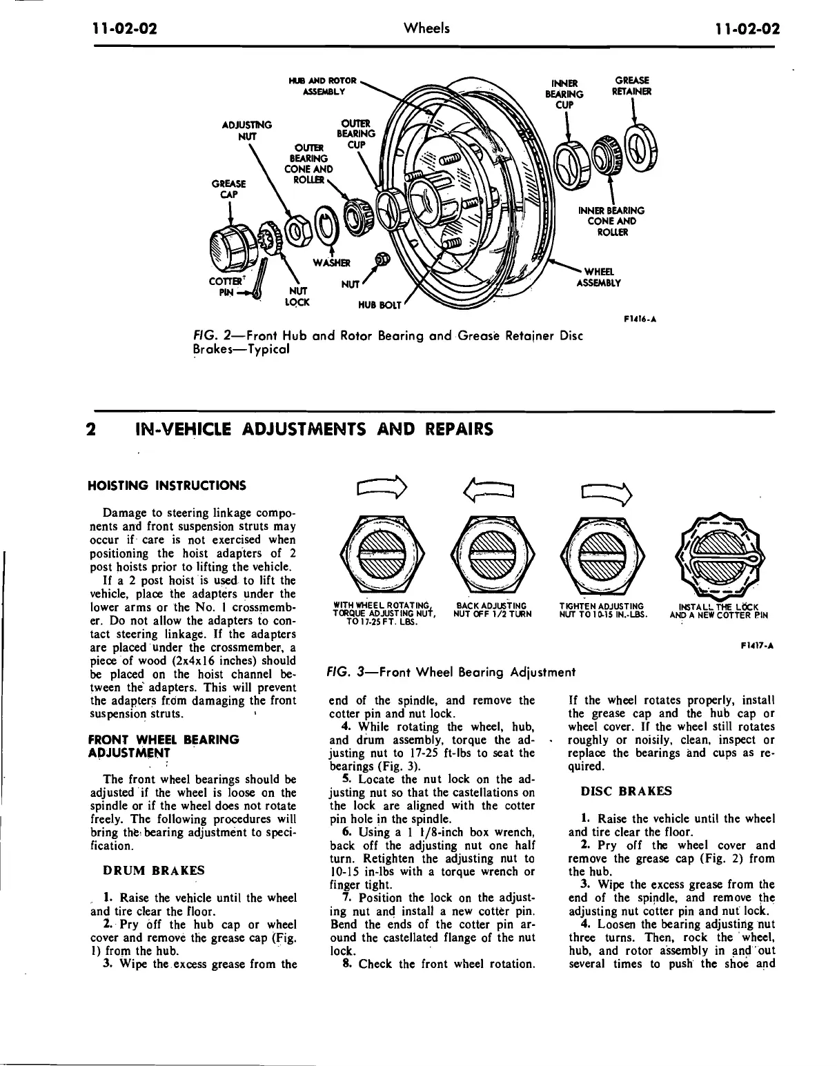
FIG. 3-Front Wheel Bearing Adjustment
end of the spindle, and remove the
cotter pin and nut lock.
4.
While rotating the wheel, hub,
and drum assembly, torque the ad-
justing nut to 17-25 ft-lbs to seat the
bearings (Fig.
3).
5.
Locate the nut lock on the ad-
justing nut so that the castellations on
the lock are aligned with the cotter
pin hole in the spindle.
6.
Using a 1 t/8-inch box wrench,
back off the adjusting nut one half
turn. Retighten the adjusting nut to
10-15 in-lbs with a torque wrench or
finger tight.
7.
Position the lock on the adjust-
ing nut and install a new cotter pin.
Bend the ends of the cotter pin ar-
ound the castellated flange of the nut
lock.
8.
Check the front wheel rotation.
If the wheel rotates properly, install
the grease cap and the hub cap or
wheel cover. If the wheel still rotates
-
roughly or noisily, clean, inspect or
replace the bearings and cups as re-
quired.
DISC BRAKES
1.
Raise the vehicle until the wheel
and tire clear the floor.
2.
Pry off the wheel cover and
remove the grease cap (Fig. 2) from
the hub.
3.
Wipe the excess grease from the
end of the spindle, and remove
the
adjusting nut cotter pin and nut lock.
4.
Loosen the bearing adjusting nut
three turns. Then, rock the 'wheel,
hub, and rotor assembly in
and-out
several times to push' the shoe and
 Loading...