12. Raise and support the vehicle. For additional information, refer to Section 100-02.
13. Remove the LH wheel and tire. For additional information, refer to Section 204-04.
14. Remove the LH transaxle support and insulator. For additional information, refer to Transaxle Support Insulator in this section.
15. Position a drain pan under the transaxle side pan.
16. NOTE: It will be necessary to lower the left side of the subframe to remove the main control cover through the wheel well.
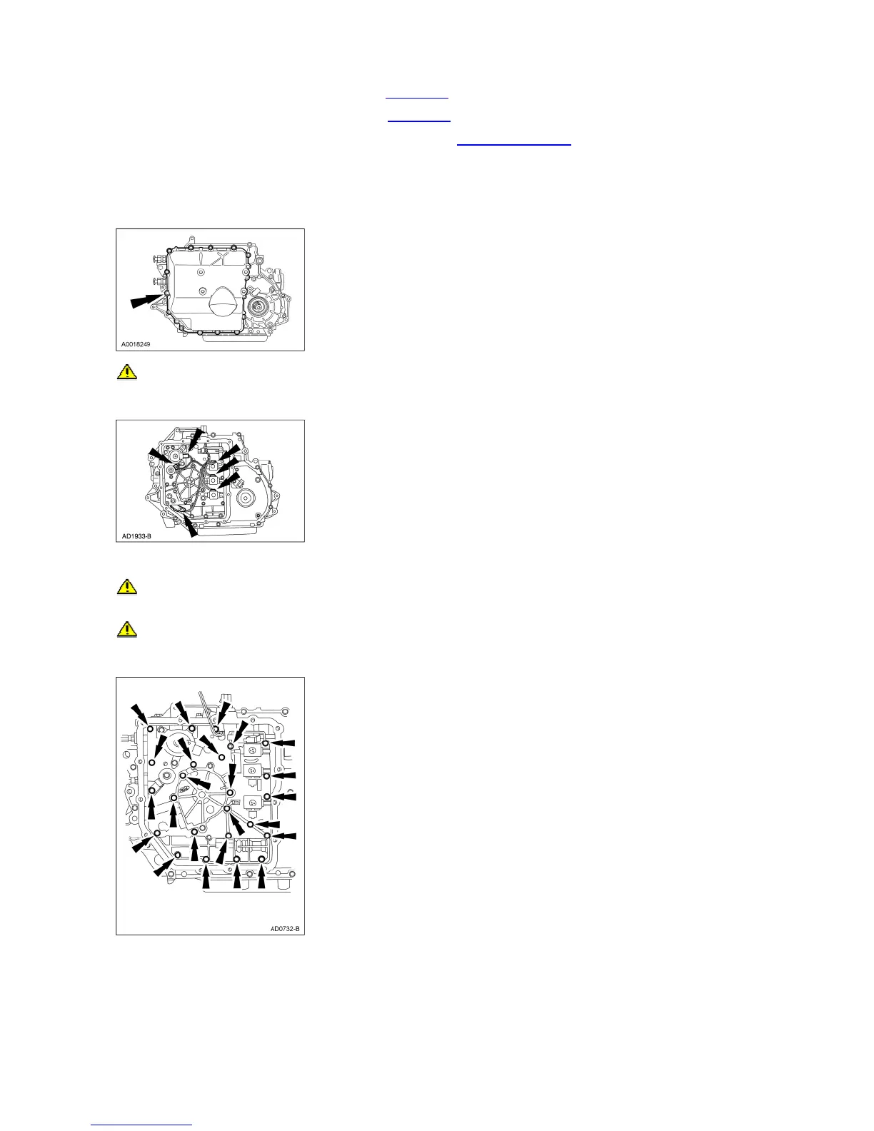
Remove the remaining bolts, and remove the main control cover.
17. CAUTION: Do not pull on the wires or the electrical connectors. Damage to the connectors will result.
Lift the locking tab and disconnect the electrical connectors.
18. Position the transaxle wiring harness out of the way.
19. CAUTION: Do not remove the two bolts that hold the pump assembly and main control valve body together as the pump assembly may fall from
the main control valve body and become damaged.
CAUTION: Only four of the six bolts need to be removed.
Remove the bolts. Note the size and location of the bolts.
20. Disconnect the manual linkage.
Remove the main pump assembly and the main control valve body by carefully sliding it off the pump shaft.
2001 Windstar Workshop Manual
http://www.fordtechservice.dealerconnection.com/pubs/content/~WS1W/~MUS~LEN/19/