Is the resistance less than 5 ohms?
REPAIR the circuit. REPEAT the FEM
self-test. CLEAR the DTCs.
A9 CHECK THE MULTIFUNCTION SWITCH FOR CORRECT OPERATION
Disconnect: Multifunction Switch C202.
Carry out the multifunction switch component test.
Refer to Wiring Diagrams Cell 149, Interval Wiper/Washer for component testing.
Is the multifunction switch OK?
Yes
GO to A10.
No
INSTALL a new multifunction switch.
REFER to Section 211-05. REPEAT the
FEM self-test. CLEAR the DTCs.
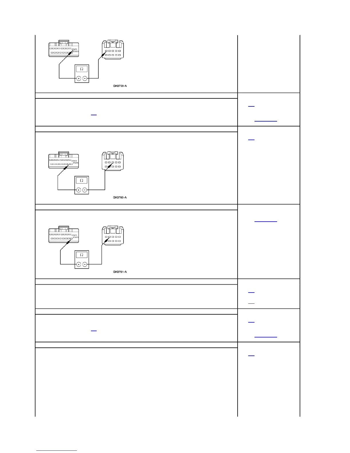
A10 CHECK CIRCUIT 1302 (WH/LG) FOR OPEN
Disconnect: FEM C201d.
Measure the resistance between the FEM C201d pin 14, circuit 1302 (WH/LG), harness side and multifunction switch C202 pin 3,
circuit 1302 (WH/LG), harness side.
Is the resistance less than 5 ohms?
Yes
GO to A11.
No
REPAIR the circuit. REPEAT the FEM
self-test. CLEAR the DTCs.
A11 CHECK CIRCUIT 1300 (VT) FOR OPEN
Measure the resistance between the FEM C201d pin 13, circuit 1300 (VT), harness side and multifunction switch C202 pin 4,
circuit 1300 (VT), harness side.
Is the resistance less than 5 ohms?
Yes
INSTALL a new multifunction switch.
REFER to Section 211-05. REPEAT the
FEM self-test. CLEAR the DTCs.
No
REPAIR the circuit. REPEAT the FEM
self-test. CLEAR the DTCs.
A12 CHECK WIPER MULTIFUNCTION SWITCH — MONITOR THE FEM PID WPMODE
Ignition OFF.
Connect the scan tool.
Ignition ON.
Enter the following diagnostic mode on the scan tool: FEM PID WPMODE, while rotating the windshield wiper switch through
each of its wiper and washer positions.
Do the PIDs agree with the switch positions?
Yes
GO to A16.
No
GO to A13.
A13 CARRY OUT MULTIFUNCTION SWITCH COMPONENT TEST
Disconnect: Multifunction Switch C202.
Check the multifunction switch for correct operation.
Refer to Wiring Diagrams Cell 149, Interval Wiper/Washer for component testing.
Is the multifunction switch OK?
Yes
GO to A14.
No
INSTALL a new multifunction switch.
REFER to Section 211-05. REPEAT the
FEM self-test. CLEAR the DTCs.
A14 CHECK CIRCUITS 1300 (VT), 1301 (YE), AND 1302 (WH/LG) FOR OPENS
Disconnect: FEM C201b.
Measure the resistance between FEM C201d pin 13, circuit 1300 (VT), harness side and multifunction switch C202 pin 4, circuit
1300 (VT), harness side; and between FEM C201d pin 2, circuit 1301 (YE), harness side and multifunction switch C202 pin 5,
circuit 1301 (YE), harness side; and between FEM C201d pin 14, circuit 1302 (WH/LG), harness side and multifunction switch
C202 pin 3, circuit 1302 (WH/LG), harness side.
Yes
GO to A15.
No
REPAIR the circuit as necessary.
REPEAT the FEM self-test. CLEAR the
DTCs.
Page 4 of 172003 Windstar Workshop Manual
8/17/2010http://www.fordtechservice.dealerconnection.com/pubs/con...
 Loading...