GO to B9.
B2 CHECK THE REAR WIPER RELAY
Disconnect: Rear Wiper Relay.
Check the rear wiper relay for correct operation.
Refer to Wiring Diagrams Cell 149, Interval Wiper/Washer for component testing.
Is the rear wiper relay OK?
Yes
GO to B3.
No
INSTALL a new rear wiper relay. REPEAT the FEM self-test.
CLEAR the DTCs.
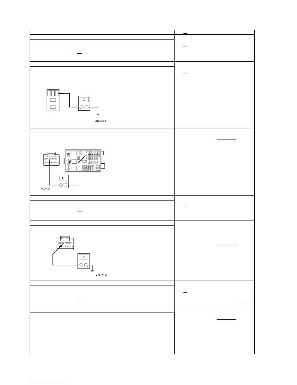
B3 CHECK CIRCUIT 1359 (DG/VT) FOR SHORT TO GROUND
NOTE: Make sure that the rear wiper is turned OFF.
Measure the resistance between rear wiper relay pin 1, circuit 1359 (DG/VT), harness side and ground.
Is the resistance greater than 10,000 ohms?
Yes
GO to B4.
No
REPAIR the circuit. REPEAT the FEM self-test. CLEAR the
DTCs.
B4 CHECK CIRCUIT 1359 (DG/VT) FOR OPEN
Disconnect: FEM C201a.
Measure the resistance between FEM C201a pin 4, circuit 1359 (DG/VT), harness side and rear wiper relay
pin 1, circuit 1359 (DG/VT), harness side.
Is the resistance less than 5 ohms?
Yes
INSTALL a new FEM. REFER to Section 419-10. REPEAT the
FEM self-test. CLEAR the DTCs.
No
REPAIR the circuit. REPEAT the FEM self-test. CLEAR the
DTCs.
B5 CHECK REAR WIPER RELAY FOR CORRECT OPERATION
Check the rear wiper relay for correct operation.
Refer to Wiring Diagrams Cell 149, Interval Wiper/Washer for component testing.
Is the rear wiper relay OK?
Yes
GO to B6.
No
INSTALL a new rear wiper relay. REPEAT the FEM self-test.
CLEAR the DTCs.
B6 CHECK CIRCUIT 1359 (DG/VT) FOR SHORT TO VOLTAGE
Measure the voltage between FEM C201a pin 4, circuit 1359 (DG/VT), harness side and ground.
Is the voltage greater than 10 volts?
Yes
REPAIR the circuit. REPEAT the FEM self-test. CLEAR the
DTCs.
No
INSTALL a new FEM. REFER to Section 419-10. REPEAT the
FEM self-test. CLEAR the DTCs.
B7 CHECK THE MULTIFUNCTION SWITCH FOR CORRECT OPERATION
Disconnect: Multifunction Switch C202.
Check the multifunction switch for correct operation.
Refer to Wiring Diagrams Cell 149, Interval Wiper/Washer for component testing.
Is the multifunction switch OK?
Yes
GO to B8.
No
INSTALL a new multifunction switch. REFER to Section 211-
05. REPEAT the FEM self-test. CLEAR the DTCs.
B8 CHECK CIRCUIT 1413 (VT/LB) FOR OPEN
Disconnect: FEM C201e.
Measure the resistance between FEM C201e pin 5, circuit 1413 (VT/LB), harness side and multifunction
switch C202 pin 2, circuit 1413 (VT/LB), harness side.
Yes
INSTALL a new FEM. REFER to Section 419-10. REPEAT the
FEM self-test. CLEAR the DTCs.
No
REPAIR the circuit. REPEAT the FEM self-test. CLEAR the
DTCs.
Page 7 of 172003 Windstar Workshop Manual
8/17/2010http://www.fordtechservice.dealerconnection.com/pubs/con...