4
WWW.FORNEYIND.COM
FOLLOW THESE STEPS WHEN BATTERY IS INSTALLED IN VEHICLE
FOLLOW THESE STEPS WHEN BATTERY IS OUTSIDE VEHICLE
1. Position the A.C. and D.C. cables to reduce the
risk of damage by the hood, door and moving or
hot engine parts. NOTE: If it is necessary to close
the hood during the charging process, ensure
that the hood does not touch the metal part of the
battery clips or cut the insulation of the cables.
2. Stay clear of fan blades, belts, pulleys and other
parts that can cause injury.
3. Check the polarity of the battery posts. The POSITIVE
(POS, P, +) battery post usually has a larger
diameter then the NEGATIVE (NEG, N, -) post.
4. Determine which post of the battery is grounded
(connected) to the chassis. If the negative post is
grounded to the chassis (as in most vehicles). If the
positive post is grounded to the chassis.
5. For a negative-grounded vehicle, connect the
POSITIVE (RED) clip from the battery charger to
the POSITIVE (POS, P, +) ungrounded post of the
battery. Connect the NEGATIVE (BLACK) clip to
1. Check the polarity of the battery posts. The POSITIVE
(POS, P, +) battery post usually has a larger diameter
than the NEGATIVE (NEG, N, -) post.
2. Attach at least a 24-inch (61 cm) long 6-gauge
(AWG) insulated battery cable to the NEGATIVE
(NEG, N, -) battery post.
3. Connect the POSITIVE (RED) charger clip to the
POSITIVE (POS, P, +) post of the battery.
4. Position yourself and the free end of the cable you
previously attached to the NEGATIVE (NEG, N,
-) battery post as far away from the battery as
possible – then connect the NEGATIVE (BLACK)
charger clip to the free end of the cable.
5. Do not face the battery when making the final
connection.
6. When disconnecting the charger, always do so in
the reverse order of the connecting procedure and
the vehicle chassis or engine block away from the
battery. Do not connect the clip to the carburetor, fuel
lines or sheet-metal body parts. Connect to a heavy
gauge metal part of the frame or engine block.
6. For a positive-grounded vehicle, connect the
NEGATIVE (BLACK) clip from the battery charger
to the NEGATIVE (NEG, N, -) ungrounded post
of the battery. Connect the POSITIVE (RED) clip to
the vehicle chassis or engine block away from the
battery. Do not connect the clip to the carburetor, fuel
lines or sheet-metal body parts. Connect to a heavy
gauge metal part of the frame or engine block.
7. When disconnecting the charger, turn all switches
to off, disconnect the A.C. cord, remove the clip
from the vehicle chassis and then remove the clip
from the battery terminal.
8. See CALCULATING CHARGE TIME for length of
charge information.
break the first connection while as far away from
the battery as practical.
7. A marine (boat) battery must be removed and
charged on shore. To charge it onboard requires
equipment specially designed for marine use.
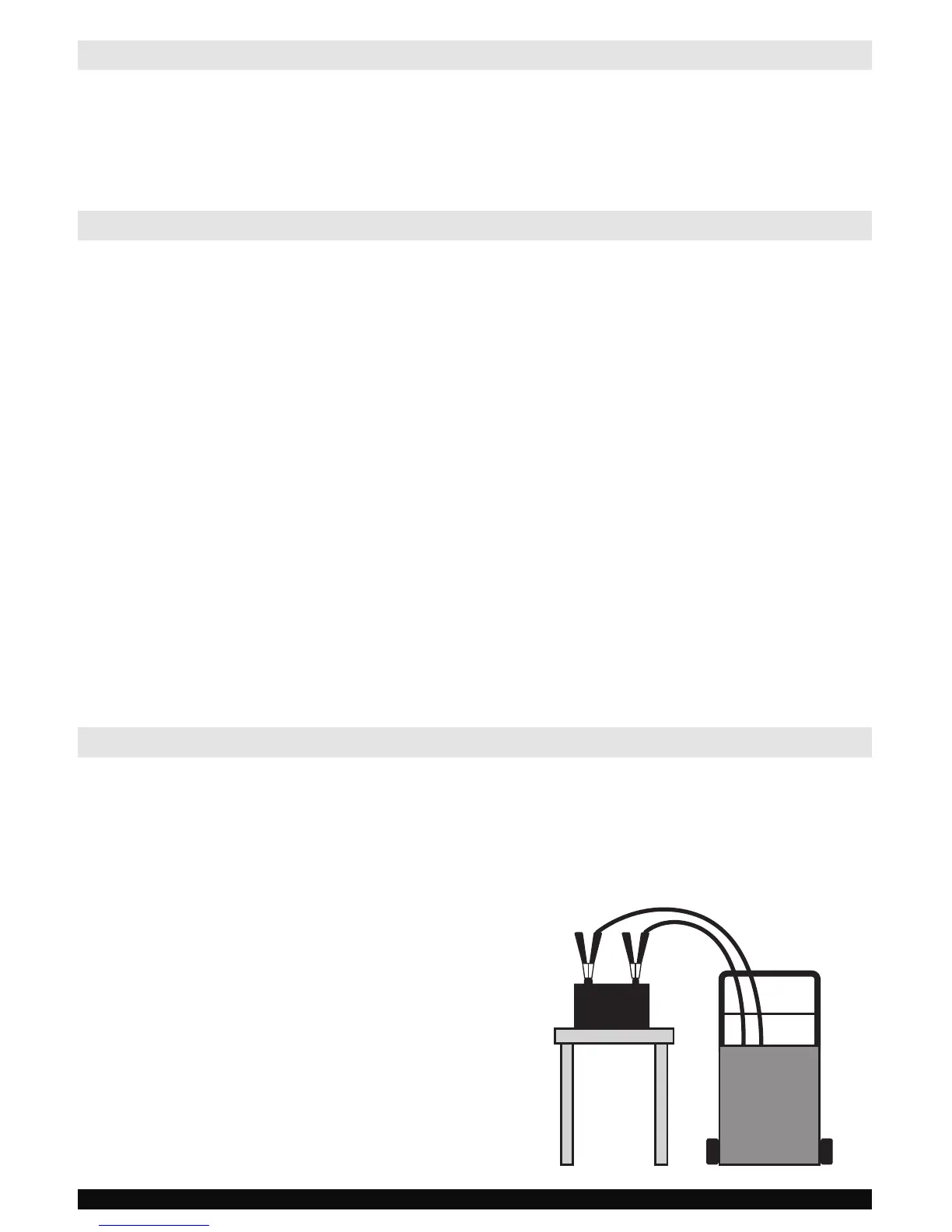
CHARGER LOCATION
1. Connect and disconnect the DC output clips only after setting all of the charger switches to the “off” position
and removing the A.C. plug from the electrical outlet. Never allow the clips to touch each other.
2. Attach the clips to the battery and chassis.
+ –
NEGATIVE
POSITIVE
BATTERY
BATTERY
CHARGER