5. Hardware Integration
The I/O cable described in section 4.5 provides the connections required for most integration into systems
with a user computer, wired emergency stops, and utilizing the Master Enables.
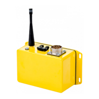
Estop_In_0/Estop_out_0 and Estop_In_1/Estop_out_1 are intended to be connected as shown through a
standard emergency stop switch. These signals are internally biased to their fault state, so if this wired
safety input is not used it must be bypassed externally as shown below. It is critical that the Estop_In_0
and Estop_In_1 signals are treated properly. If one or both signals are treated improperly or left
unconnected, the VSC will treat this as a fault condition and de-assert the Master Enable signals.
Figure 6 – Emergency Stop Input Wiring
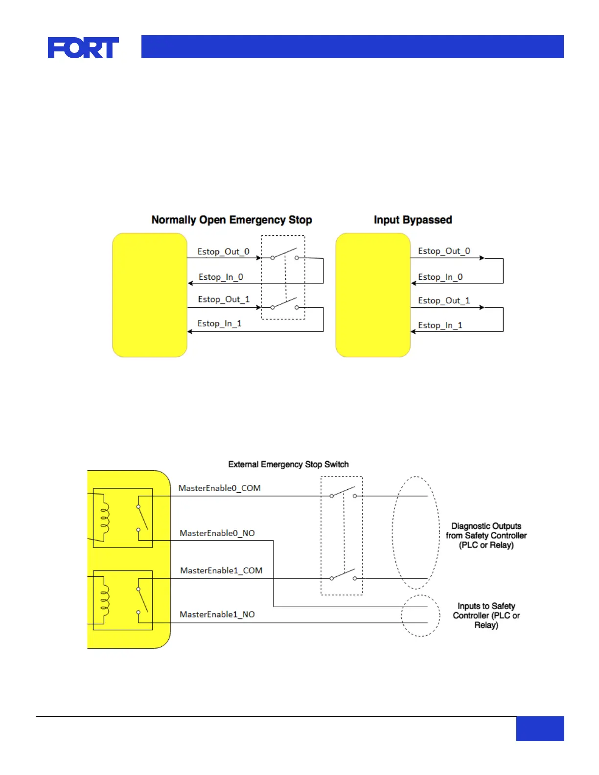
Access to the internal safety relays are given through the MasterEnable_NO and MasterEnable_COM
signals. One normally open contact of each of the two relays is provided for control of external loads
(motors, contactors, or relays) or participation in an existing wired emergency stop loop. This architecture
makes the VSC integrate similarly to an additional wired normally open emergency stop button.
Figure 7– Master Enable Connection to Emergency Stop Loop
 Loading...