VEHICLE SAFETY CONTROLLER
© 2021, FORT Robotics. Company Confidential. Do not distribute. 935-0003 Rev C
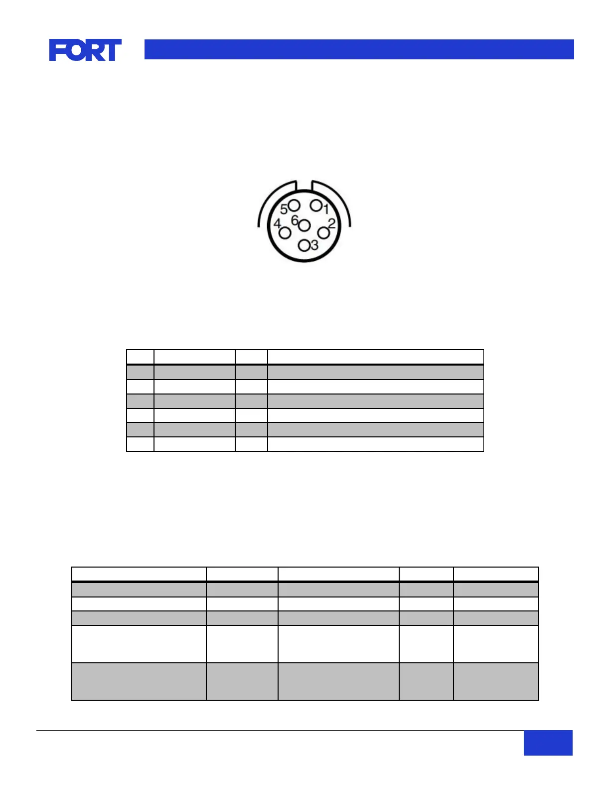
4.6. USB Connector Pinout
4.6.1. VSC-009 - 38999
The 6-pin USB connector is used primarily for configuration and firmware upgrades or system
communication if the USB-CDC interface is utilized.
Figure 3 - VSC USB connector pin location
NOTE: Connectors are designed to be hand tightened only. Use of a wrench or other tool will cause damage
to the connector or cabling.
Reserved. Do Not Connect.
Reserved. Do Not Connect.
USB data negative differential signal
USB data positive differential signal
Table 9 –VSC USB (VIC-004) connector pinout and signal descriptions
4.6.2. VSC-006 – USB Mini-AB
The standard USB Mini-AB connector is used primarily for configuration and firmware upgrades or system
communication if the USB-CDC interface is utilized.
4.7. Mechanical Specifications
4.7.1. VSC-009 – 38999
38999 Series III TV 6p
(Amphenol part #
D38999/24WA35PN)
38999 Series III TV 19p
(Amphenol part #
D38999/24WD19PN)
1 – When connected or dustcap installed
Table 10 –VSC-009 Mechanical Specifications
 Loading...