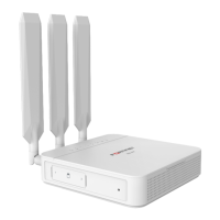
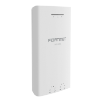
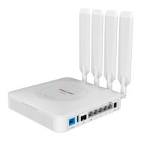
The FortiExtender 511F is a wireless Internet WAN connection device designed to provide robust and flexible connectivity solutions. It supports both Sub-6 GHz 5G wireless connections and 4G LTE CAT 20 connections, making it versatile for various network environments.
Function Description
The FortiExtender 511F serves as a wireless WAN extender, providing internet connectivity through 5G or 4G LTE networks. It can be integrated with FortiGate appliances to extend network reach and provide reliable internet access. The device is designed to offer high-speed wireless connectivity, with a maximum downlink speed of 5 Gbps and an uplink speed of 650 Mbps in NSA mode for 5G, and a maximum downlink speed of 4.2 Gbps and an uplink speed of 450 Mbps in SA mode. For 4G LTE, it supports a maximum downlink speed of 2 Gbps and an uplink speed of 200 Mbps.
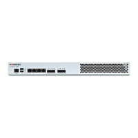
The device includes a 1G SFP connection, one 1G RJ-45 wired WAN connection, and four 1G LAN connections, allowing for flexible integration into existing network infrastructures. It supports Power over Ethernet (PoE) on LAN 4/PoE PD port, simplifying installation by allowing power and data to be transmitted over a single Ethernet cable.
Important Technical Specifications
Wireless Connectivity:
- 5G Sub-6 GHz:
- NSA mode: 5 Gbps downlink, 650 Mbps uplink.
- SA mode: 4.2 Gbps downlink, 450 Mbps uplink.
- Supports MicroSIM (3FF) SIM cards.
- 4G LTE CAT 20:
- 2 Gbps maximum downlink speed.
- 200 Mbps maximum uplink speed.
- Antennas: Four external 5G/LTE/GNSS All-in-One Antennas.
Ports and LEDs:
- USB 2.0 Port: For peripheral connections.
- SFP Port: One 1G SFP connection.
- WAN Port: One 1G RJ-45 wired WAN connection.
- LAN Ports (1-4): Four 1G RJ-45 LAN connections. LAN 4 is PoE PD LAN (802.3at).
- Console Port: For device configuration (baud rate 115200).
- 12V/2A Input: Optional power input (ID 2.1 mm plug).
- Kensington Lock Slot: For physical security.
- Bluetooth LED: Indicates Bluetooth status.
- SIM Slot Cover: Protects the SIM card slots.
- Bluetooth Button: For Bluetooth configuration.
- Reset/Default Button: For resetting the device or restoring factory defaults.
LED Behavior:
- SFP LED:
- Green Steady: 1G network connection.
- Green Flashing: 1G network activity.
- OFF: No network connection.
- RJ45 Network LEDs:
- Green Steady: 1G network connected.
- Green Flashing: 1G network activity.
- Amber Steady: 100M network connected.
- Amber Flashing: 100M network activity.
- OFF: No network connection.
- Bluetooth LED:
- Green Steady: Bluetooth configuration window is open (upon pressing the Bluetooth button). Closes in 30 seconds if no configuration is performed.
- Blue Flashing: Bluetooth configuration is in progress.
- Blue Steady: Bluetooth configuration is completed. The LED turns off in 5 seconds.
- OFF: No Bluetooth configuration is allowed.
- Power LED:
- Green Steady: System has booted up and is working properly.
- Green Flashing: System is booting up.
- Amber: System is in error state.
- OFF: System is powered off.
- LTE Mode LED:
- Green: System is running in LTE connection mode.
- OFF: System is not in LTE mode.
- 5G Mode LED:
- Blue: System is running in 5G connection mode.
- OFF: System is not in 5G mode.
- Management LED:
- Blue Steady: System is managed by FortiGate or FortiExtender Cloud.
- Blue Flashing: System is connecting to a managing device.
- OFF: System is running in stand-alone mode.
- FortiSASE/LAN Extension LED:
- Blue Steady: System is connected to FortiSASE/LAN Extension.
- Blue Flashing (at one-second intervals): System is connecting to FortiSASE/LAN Extension.
- Blue Flashing Rapidly (at less-than-one-second intervals): System is experiencing an error in connecting to FortiSASE/LAN Extension.
- OFF: System is not configured for FortiSASE/LAN Extension.
- 5G/LTE LED:
- Blue Steady: 5G module connected to carrier and works properly.
- Green Steady: 5G module connected to wireless carrier in LTE mode and works properly.
- Green Flashing: 5G module is booting up and connecting to wireless carrier.
- Green Rapid Flashing: 5G module is detected, but is experiencing SIM or firmware error.
- OFF: 5G module is not detected.
- 5G/LTE Signal Strength LEDs (Blue=5G; Green=LTE):
- 1 On: < 25%.
- 1 & 2 On: 25% - 50%.
- 1, 2 & 3 On: 50% - 75%.
- 1, 2, 3, & 4 On: > 75%.
Usage Features
Basic Connections:
- Ethernet Cable Connection: Insert one end of an Ethernet cable into the LAN 4/PoE PD port on the device and the other end into a WAN port of a FortiGate appliance or a power injector. The FortiGate interface provides DHCP server service to issue an IP address to the FortiExtender when connected to LAN Port 4.
- Optional Power Connection: If not using PoE, connect the device to a power outlet using a power adapter.
SIM Card Assembly:
- Remove the dust cover that protects the SIM sockets.
- Insert two MicroSIM (3FF) SIM cards into the SIM sockets (SIM1 as primary, SIM2 as secondary).
- Insert the SIM card(s) into the SIM socket(s), ensuring the card is facing down with the cut corner on the left.
- Replace the cover and attach the antennas.
IP Configuration:
- Connect an Ethernet cable from the LAN ports to the Ethernet port of a computer.
- Set the computer Ethernet port to DHCP mode and connect it to port1, port2, or port3.
- Open a web browser and point to the default FortiExtender web GUI address:
http://192.168.200.99.
- Enter
admin as the username and press Enter. The password needs to be changed for the first time.
- Navigate to Networking > Interface to see all system interfaces.
- Select a desired interface, set it to "static" mode, configure the static IP address, and click Save.
Installation Options:
- Desktop/Flat Surface Placement:
- Attach the rubber feet to the four corners on the bottom of the unit.
- Place the unit on a desk or flat surface.
- Secure the unit in place with a Kensington lock.
- Attach the antennas.
- Wall Mounting:
- Peel off the drill template sticker and stick it onto the wall in the desired location.
- Use the template to mark and drill the pilot holes.
- Insert the anchors into the holes.
- Insert the screws into the anchors and tighten, leaving around a 5-mm gap between the screw head and the wall.
- Position the device so that the mounting holes line up with the screws.
- Place the mounting slots over the screws and slide the device down until the screws fit into the slots.
- Tip: Use bear claw screws for better fit with hanging holes.
- Fasten onto a Wall:
- Peel off the drill template sticker and stick it onto the wall.
- Use the template to mark and drill the pilot holes.
- Insert the anchors into the holes.
- Snap off the plastic cover over the LEDs on the front to reveal the long screw holes.
- Insert the long screws through the device from front to back.
- Insert the long screws into the anchors on the wall and tighten.
- Replace the cover over the LEDs on the front.
Maintenance Features
Control Button Usage:
- Reset/Default Button:
- Press and hold for less than 5 seconds: Reset/Reboot the device.
- Press and hold for more than 5 seconds: Restore the device to its factory default settings.
- Bluetooth Button:
- Press and hold for less than 5 seconds: Ignored.
- Press and hold for more than 5 seconds: Turns on Bluetooth LED, and opens Bluetooth configuration window. The window closes if no Bluetooth configuration activity occurs within 30 seconds. Re-pressing the button has no effect while Bluetooth configuration is in progress or if it is completed within 5 minutes.
Firmware and Software Updates:
Fortinet provides regular firmware updates to enhance performance, security, and add new features. Users are encouraged to register their product for support and access the latest documentation and software releases.
Support and Documentation:
- Product Registration: Registering the FortiExtender 511F provides access to technical support, new product features, and protection from new threats.
- Fortinet Customer Service & Support: Create a support account, register and manage products, download updates, firmware images, and release notes, and create technical support tickets via
https://support.fortinet.com.
- Fortinet Document Library: Access up-to-date versions of Fortinet publications for all Fortinet products via
https://docs.fortinet.com.
- Training Services: Find course descriptions, availability, schedules, and locations of training programs via
https://training.fortinet.com.
- Technical Discussion Forums: Communicate with other customers and Fortinet partners about Fortinet products, services, and configuration issues via
https://forum.fortinet.com.
- FortiGuard Threat Research and Response: Get up-to-date information on vulnerabilities and threats, including a virus scanner, IP signature look-up, and web filtering tools via
http://www.fortiguard.com.
Environmental Specifications:
- Ambient Operating Temperature: 0°C to 40°C.
- Storage Temperature: -20°C to 70°C.
- Humidity: 10% to 90% non-condensing.
Regulatory Compliance:
The device complies with various regulatory standards, including FCC, ISED (Innovation, Science and Economic Development Canada), and CE (European Conformity). It is designed to operate within specified radio frequency ranges and power limits to ensure minimal interference and safe operation. Users should ensure that the device is installed and operated with a minimum distance of 20cm between the radiator and their body to comply with FCC radiation exposure limits.