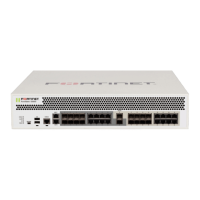
# Interface Type Description
1 Power Supply 100-240V AC, 5.8-2.9A, 50-60Hz, redundant
power supplies.
2 SFP Ports
1 to 48
SFP+ 10Gbps/auto, small form-factor pluggable
transceiver ports.
3 QSFP+ Ports
49 to 52
QSFP+ 40Gbps quad small form-factor pluggable
transceiver ports.
4 Console Port RJ-45
Optional connection to the management
computer. Provides access to the CLI.
5 MGMT Port RJ-45 Gigabit Ethernet client port for management.
The default IP address is 192.168.1.99.
Caution: SFP ports should use UL listed Optical Transceiver products, rated
Laser Class 1, 3.3V DC.
Technical Specifications
1 3 5 7 9 11
2 4 6 8 10 12
13 15 17 19 21 23
14 16 18 20 22 24
25 27 29 31 33 35
26 28 30 32 34 36
37 39 41 43 45 47
38 40 42 44 46 48
49 50
51 52
CONSOLE
PWR1 PWR2 SYSTEM FAN
MGMT
3
4
# LED State Description
1 PWR 1 & 2
Green The power supply is powered.
Flashing Yellow The power supply has failed.
Off Power is not connected.
2 SYSTEM
Green
The unit is operating normally.
Flashing Green
The unit is booting up or in
diagnostic mode.
Red
The unit has a major alarm.
Off The unit is off.
3
SFP and
QSFP Ports
Green Port is active.
Flashing Green
Port is transmitting and receiving
data.
Off
No link established.
4
Ethernet Ports
Speed
Green Port is connected at 1Gbps.
Yellow Port is connected at 10/100Mbps.
Off No link established.
4
Ethernet Ports
Activity
Flashing Green
Port is transmitting and receiving
data.
Off
Port is not in use.
LED Specifications 1
Page 9Page 8
1 3 5 7 9 11
2 4 6 8 10 12
13 15 17 19 21 23
14 16 18 20 22 24
25 27 29 31 33 35
26 28 30 32 34 36
37 39 41 43 45 47
38 40 42 44 46 48
49 50
51 52
CONSOLE
PWR1 PWR2 SYSTEM FAN
MGMT
2 31 1
4
 Loading...