14
Installation of the unit into the Cabinet
Installation of the unit into the wall
1. Slide the unit into the cabinet until it is firmly against the
rear of the cabinet. Ensure the foam
sealing strips on the cabinet remain in position.
2. Connect the air conditioner to the power and put
excess cord on the air conditioner base.
3. Engage the chassis fixing brackets into the bottom cabinet
rail and secure to the base with the screw provided.
4. Remove the front panel from the carton and plastic bag
and fit as per the Installation lnstruction.
5. Switch unit on to check for operation of the unit and
vibration in the installation.
6. Fit the drain pan to the cabinet and run a drain tube to a
suitable location if required.
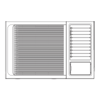
Alternative method of installation if external
support cannot be provided.
FLASH OR SEAL AR
OUND EXTERNAL
WALL FRAME OR ARCHITRAVE
STURDY TIMBER
FRAME
TIMBER FRAMED
WALL OR P
ARTITION
SOLID TIMBER SUPPORT
STEADYING BRACKET
(ONE PER SIDE)
DRAIN TRAY
ENSURE LOUVRES
ARE ENTIRELY
OUTSIDE
THE WALL
Step 1
Remove the air conditioner from the
package, remove fixing
screws and slide the air conditioner out from the cabinet (Refer
to Installation Steps).
Step 2
Drill holes in the wall to ensure the cabinet can be well
supported. Holes from the outside through to the cavity should be
sealed. The cabinet should slope down towards the rear by
about 10mm to allow water drainage during operation.
Step 3
Install and secure the cabinet into the wall. Ensure the foam
seals are not damaged. Flash, seal or fill gaps around the
inside and outside to provide satisfactory appearance and
protection against the weather, insects and rodents.
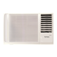
Installation of the
Cabinet
NOTE: UNIT CAN BE SUPPORTED BY
A
SOLID FRAME FROM BELOW OR
BY A HANGER FROM A SOLID
OVERHEAD SUPPORT.
Preferred method of installation into a timber
framed wall, partition or window.
FLASH OR SEAL AROUND EXTERNAL
W
ALL FRAME OR ARCHITRAVE
STURDY TIMBER
FRAME ALL R
OUND
UNIT
TIMBER FRAMED
WALL OR P
ARTITION
EXTERNAL SUPPORT
FRAME A
T BALANCE
POINT OF A/C
ALTERNATIVEL
Y, BRACKETS
AS ILLUSTRATED BELOW
MAY BE USED.
DRAIN TRAY
O
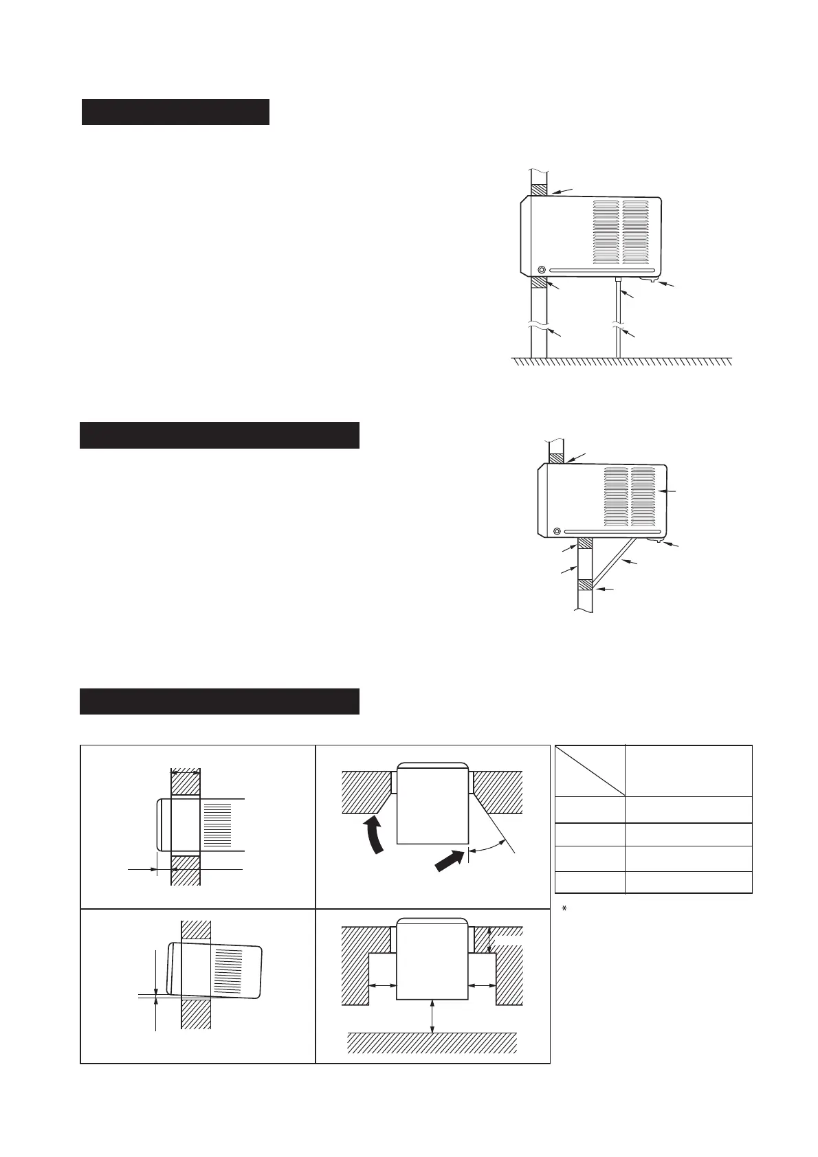
45
Scrape
10mm
Less than C
more than D
More than A
More than B
Less than
Wall thickness is less than C
If the wall thickness is more than
scrape the wall as shown above.
Make rear side lower so that water will drain
out smoothly.
C
C
Size(mm)
A
B
C
D
200*
500
210
60
The minmum
gap between
the wall
and the cabinet or air inlet louvers:
Position A is determined
by
the specific model and
environment, however,
the installation distance
must not be less than 200 mm.
More than A
 Loading...