Page 7For technical questions, please call 1-888-866-5797.Item 57336
SAFETYOPERATIONMAINTENANCE INSTALLATION
Assembly
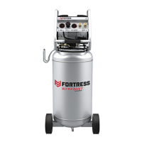
Attach Wheel
1. After unboxing, leave compressor on base inside of
tray. Fold down edges of tray and attach Wheels.
2. Attach Wheels to brackets on Tank,
using Axle Bolts (1), Flat Washers (3),
Spring Washers (4), and Nuts (5).
Wheel
Bracket
on Tank
Spring
Washer
(4)
Flat
Washer
(3)
Nut
(5)
Axle
Bolt
(1)
Attach Hose Hook
Hose Hook can be installed on
either side of Compressor.
1. Remove Nuts (72 & 73) from
either side of Compressor.
2. Place Hose Hook over Bolts and secure with Nuts.
Cap Nut
(72)
Bolt
Nut (73)
Hose
Hook
Breaking in the Compressor
1. Turn the Power Switch OFF and unplug Power Cord.
2. Fully open Drain Valve.
3. Plug in the Power Cord.
4. Turn the Power Switch ON (AUTO).
5. Let the unit run for 30 minutes.
Air will expel freely through the Drain Valve.
6. Turn the Power Switch OFF.
7. Unplug the Power Cord and close Drain Valve.
Air Connection Setup
1. Connect a regulator valve, an inline shut off valve
and a 1/4″ NPT air hose to the Quick Coupler
(all sold separately). The air hose must be long
enough to reach the work area with enough extra
length to allow free movement while working.
Note: An in-line shutoff ball valve is an important
safety device because it controls the air supply even
if the air hose is ruptured. The shutoff valve should
be a ball valve because it can be closed quickly.
2. Depending on the tool that will be used
with this compressor, incorporate additional
components, such as an in-line oiler, a filter,
or a dryer (all sold separately), as shown on
Figure A on page 8 and Figure B on page 9.
Consult air tool’s manual for needed accessories.
 Loading...