The switch (A) fig. 14 is located on the left of drill press’ head. To start the machine, push the
green button “I” of the switch (ON); to stop it, push the red button “O” of the switch (OFF).
The switch of this tool is an undervoltage switch that prevents the drill press from starting
automatically in case of restart of the electric current after an interruption; then when an
interruption of the electric current occurs the drill press stops and to make it restart you have to
push the green button again.
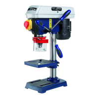
F11-951 DRILL PRESS
F11-951 drill press’ workbench can be moved up and down or turned behind the column by
loosening workbench’s lock lever (A) fig. 15. Move the bench along the column in the desired
position and tighten workbench’s lock lever (A).
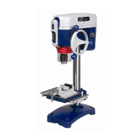
F11-991 DRILL PRESS
F11-991 drill press’ workbench can be moved up and down or turned behind the column:
loosen the lock lever then turn the handle to lift it or lower it and lock the lever; to move it behind
loosen the lever, move the workbench behind by hand and lock the lever.
The bench can also be angled to the left or to the right by loosening the rag bolt fig. 16 located
under the bench with a 19 mm wrench. A graduated plate on the fixing support of the bench
and a pointer on the bench allows you to check workbench’s angle. Place the bench at the
desired angle and tighten the bolt.
A return spring located in the box (A) fig. 17 grants the automatic return of the spindle up after
drilling. This spring has been adjusted during assembly and must not be touched. In case you
have to adjust it, proceed as described below:
1. Switch off the drill press and disconnect it from the power supply.
2. Loosen the two nuts (B) fig. 17, of 6 mm about. Do not remove these nuts (B) from the
axle (C).
3. While holding the spring box (A) fig. 17, remove it and turn it until the tongue (D) adapts to
the following tooth of the box. Turn the box to the left to increase spring tensioning and to
the right to decrease it. Then tighten the two nuts (B) that keep the box in its position.
IMPORTANT: The inner nut (B), after being tightened, does not get in contact with the
spring box (A).
ADJUSTMENT OF SPINDLE’S RETURN SPRING